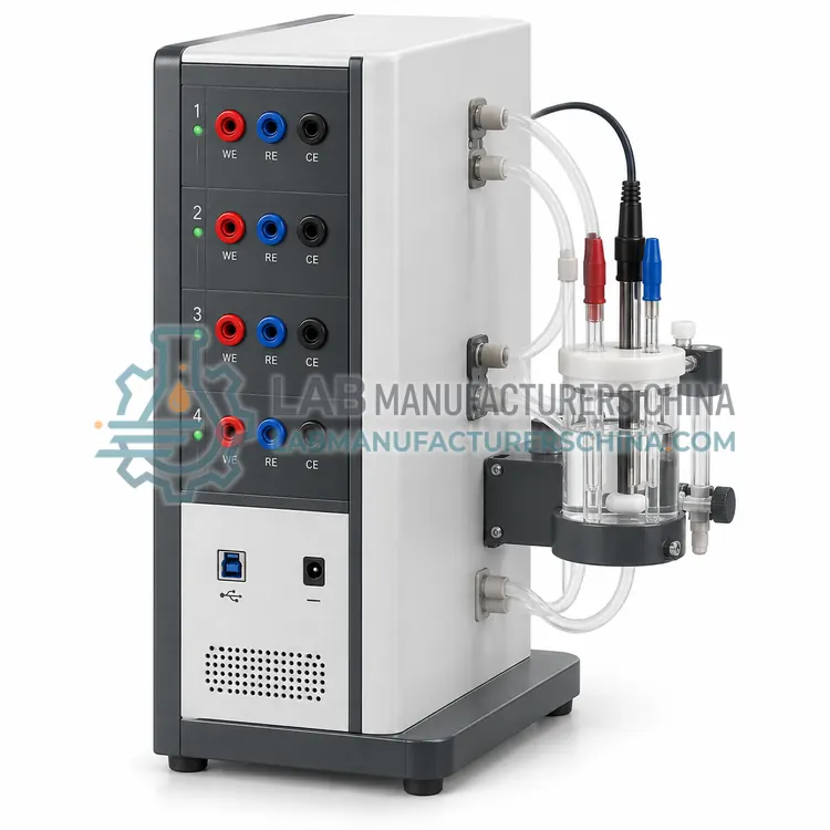
How do Potentiostats work?
Measurements use a three-electrode cell. The potentiostat applies a programmed potential between the working and counter electrodes, while a high-impedance input senses the reference electrode. A control amplifier continuously adjusts the cell current so the working electrode potential equals the set value, and a current-to-voltage converter measures that current across a selectable resistor, giving current ranges that can span twelve decades on one instrument. Compliance or output voltage, typically plus or minus 12 to 20 V, sets how much current can be delivered in high-resistance cells. In galvanostat mode the instrument controls current and monitors potential instead. A frequency response analyzer superimposes small-amplitude sine waves for impedance measurements over frequencies from microhertz to megahertz. Resolution is limited by the analog-to-digital converter and by noise from cables, stirring and the reference electrode, which is why shielded cells and a Faraday cage are common. Software controls the waveform, records data and fits the electrochemical model.
Which Potentiostats variants are available?
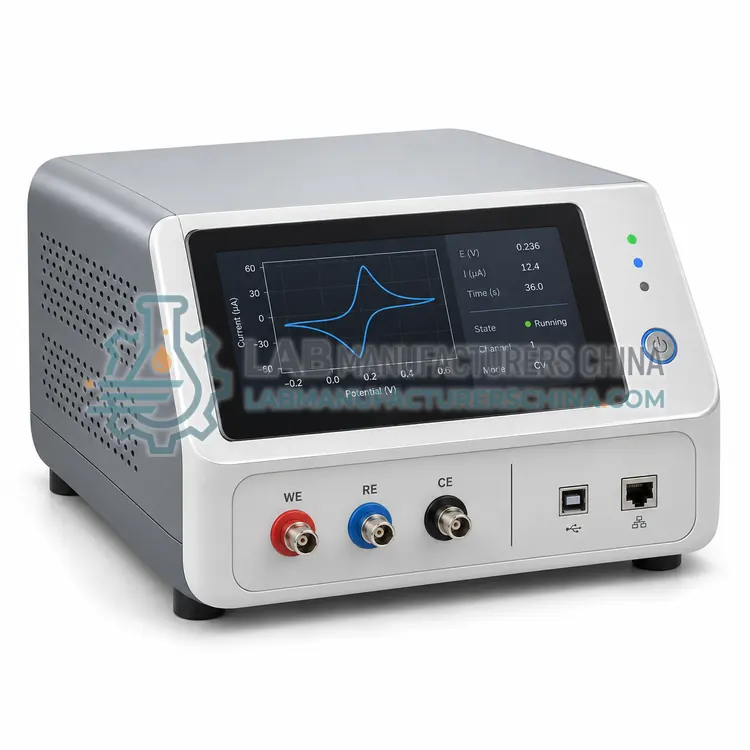
- Single-Channel Potentiostat/Galvanostat — A single-channel potentiostat/galvanostat controls one three-electrode cell with current ranges from picoamperes to amperes and built-in impedance capability.
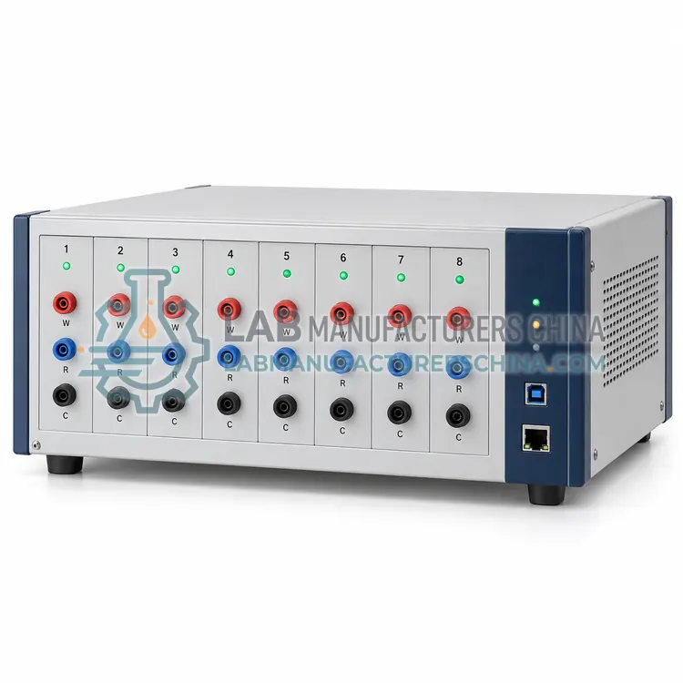
- Multichannel Potentiostat/Galvanostat — A multichannel potentiostat/galvanostat controls several three-electrode cells at once, with eight to sixty-four channels sharing one control computer.
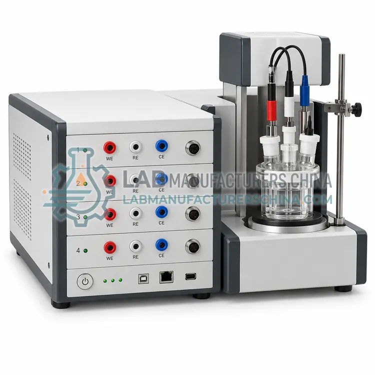
- Modular Potentiostat/Galvanostat — A modular potentiostat/galvanostat separates the control unit, potentiostat module, current booster and impedance module into interchangeable parts.
- Bipotentiostat — A bipotentiostat independently controls two working electrodes in one cell sharing a single reference and counter electrode.
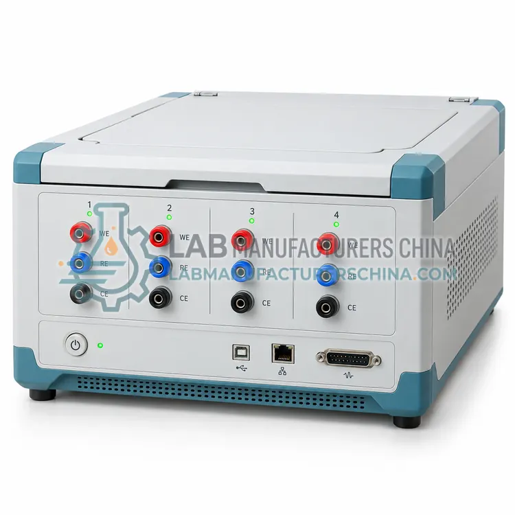
- Portable USB Potentiostat — A portable USB potentiostat is a small, bus-powered instrument that connects to a laptop and covers common voltammetric and impedance techniques at reduced current and voltage ratings.
How do I choose the right variant?
Choose the number of cells you must run at once, because multi-channel instruments cost less per channel than separate units and share one software licence. Then match current range and resolution to the application: corrosion and battery tests need amperes with moderate resolution, while microelectrode and sensor work needs picoampere resolution. Check the compliance voltage for high-resistance electrolytes, the impedance frequency range, the maximum data acquisition rate for fast kinetics, and whether the software includes the techniques you use, such as cyclic voltammetry, chronoamperometry, pulsed techniques, electrochemical impedance spectroscopy and galvanostatic cycling. Modular instruments allow later expansion. For field corrosion surveys, a portable USB unit connected to a laptop is often sufficient. Specify the cell, electrodes, cables and any booster or low-current module in an RFQ.
Where are Potentiostats used?
Potentiostats are specified in corrosion and inhibitor evaluation, battery and supercapacitor testing, electrochemical sensor and biosensor development, electrocatalysis and fuel cell research and coating and surface treatment qualification.
Which standards and certifications apply?
Work with Potentiostats is commonly governed by IEC 61010-1, ISO 17475, ISO 16773-1, ASTM G5, ASTM G61 and ASTM G71. Instrument certifications such as CE marking are confirmed per configuration and never assumed.
What are the key considerations before purchase?
Install the instrument on a stable bench away from motors, pumps and switching power supplies, and connect the cell in a Faraday cage for low-current work. Use shielded cable and keep the reference electrode close to the working electrode to reduce uncompensated resistance; measure and compensate that resistance, especially in low-conductivity electrolytes. Verify performance with a dummy cell or a standard redox couple such as ferri-ferrocyanide before critical experiments. Grounding arrangements must avoid loops between the potentiostat, the cell and any peripheral equipment such as rotators, lamps or temperature baths. Calibrate the internal references annually, replace worn electrode leads and clips, and record the cell configuration, electrodes, reference type and scan parameters with each data set so results remain traceable.