Cryogenic Phase Separator
低温相分离器
- SKU CTE-0002
- Cryogenic Transfer Equipment
- CE (to be confirmed)
- ISO 9001 manufacturing (to be confirmed)
- PED 2014/68/EU conformity (to be confirmed)
Price on request — FOB / CIF quoted per order
Prices depend on configuration, quantity and destination port.
Key specifications
| Chamber volume | 0.5–3 L |
|---|---|
| Working pressure | Up to 2 bar |
| Inlet connection | DN8–DN15, bayonet or NPT |
| Outlet connection | Tube or nozzle, 6–15 mm |
| Vent type | Float valve |
| Flow rate | 2–20 L/min |
Request a quote Download brochure · to be provided
By Lab Manufacturers China Technical TeamLast reviewed Standards: ISO 21010, ISO 21009-1, EN 13458-2
What is the Cryogenic Phase Separator?
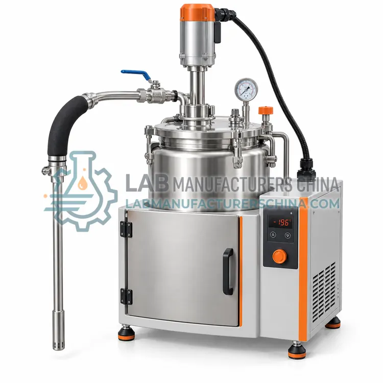
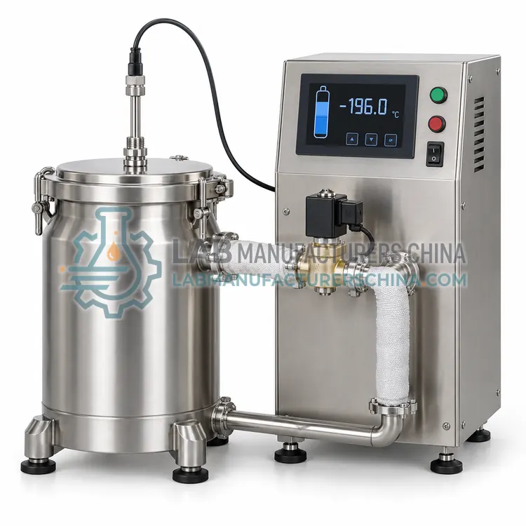
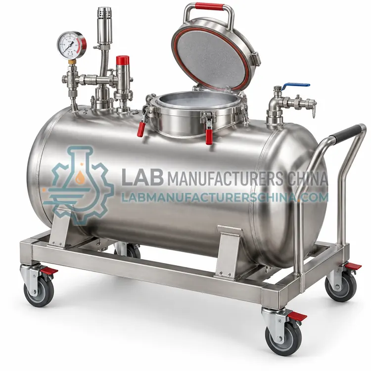
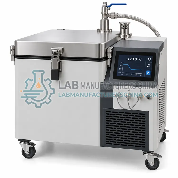
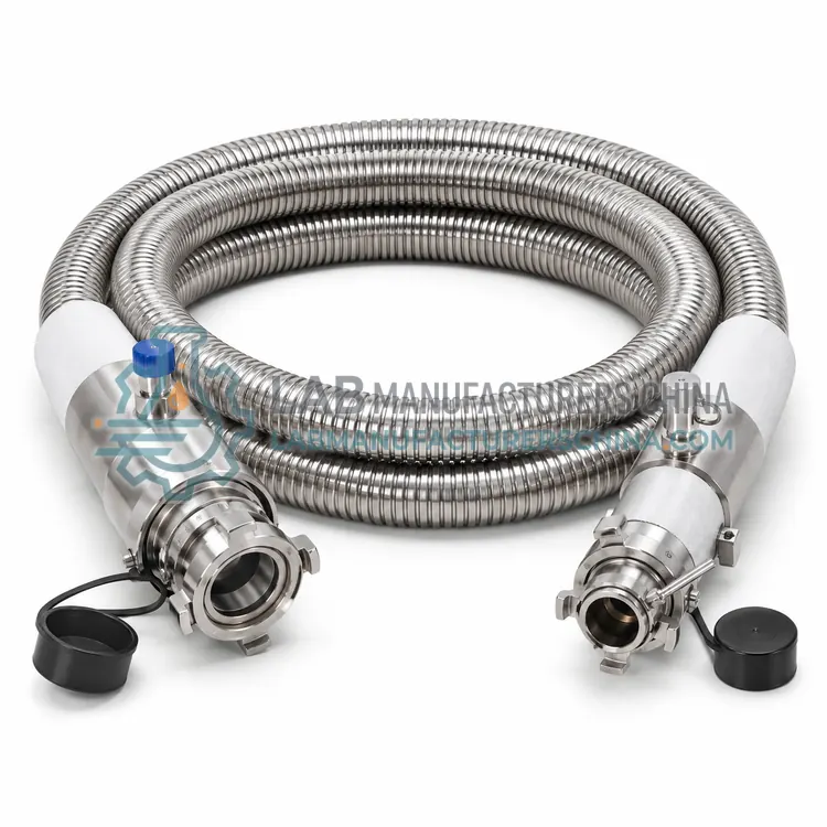
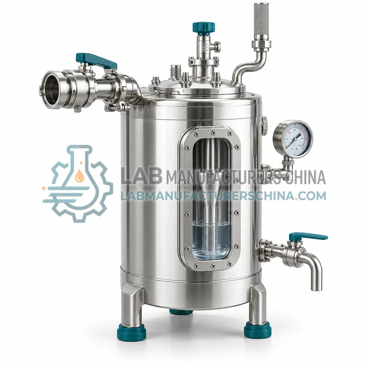
A cryogenic phase separator is a small vacuum-insulated vessel with a float-operated vent that separates nitrogen vapor from liquid at the end of a transfer line. It is the right choice for smoothly filling narrow-neck dewars, cold traps and instruments without spray or gas slugs.
What is the Cryogenic Phase Separator?
A cryogenic phase separator is a small vacuum-insulated vessel with a float-operated vent that separates nitrogen vapor from liquid at the end of a transfer line. It is the right choice for smoothly filling narrow-neck dewars, cold traps and instruments without spray or gas slugs.
Overview
When liquid nitrogen flows through a warm or partly cooled line, some of it flashes to gas, and the mixture can spray or push liquid out of narrow openings. The phase separator receives the two-phase flow in a small chamber, typically 0.5–3 L, where the liquid settles and vapor rises to a vent. A float valve or level-dependent vent keeps the vent closed when liquid is present and opens it when vapor accumulates, so that only liquid leaves through the outlet. The body is vacuum-insulated stainless steel, and connections are sized to match hose fittings, with a pressure relief valve in case the vent blocks. Separators can be fixed on a dewar's neck, on a stand or on a transfer hose end. They reduce liquid nitrogen use by limiting splash and gas loss, and they improve filling accuracy when combined with a level probe.
How does it work?
Cryogenic transfer equipment reduces heat leak while liquid moves from a source vessel to a destination. Liquid is driven either by vessel pressure, by a self-pressurizing circuit that raises headspace pressure to about 0.5–1.5 bar, or by a cryogenic pump with a submerged or extended-shaft impeller. Vacuum-jacketed hoses and pipes suppress heat transfer with an evacuated annulus and multilayer insulation, so less liquid flashes to gas in the line. A phase separator placed at the outlet vents vapor through a float-operated valve so that only liquid flows to the receiving vessel, stabilizing filling. Auto-fill controllers combine level sensors, temperature sensors and solenoid valves that open when liquid is needed and close when level is reached, with timeout and fault alarms.
What are the key features?
- Float-operated vent releases vapor while keeping liquid inside.
- Vacuum-insulated stainless steel body limits heat gain.
- Connections sized for common transfer hose fittings.
- Relief valve protects against vent blockage.
- Mounts on a dewar neck, stand or hose end.
- Reduces splashing and improves filling accuracy with level probes.
What are the technical specifications?
A typical cryogenic phase separator configuration offers chamber volume of 0.5–3 L, working pressure of Up to 2 bar, inlet connection of DN8–DN15, bayonet or NPT, outlet connection of Tube or nozzle, 6–15 mm, vent type of Float valve and flow rate of 2–20 L/min. Values are indicative of the product class; the exact figures for each configuration are confirmed on the quotation and the calibration documents supplied with the instrument.
Which applications is it used for?
The Cryogenic Phase Separator is used in filling narrow-neck dewars, cold trap refilling, instrument liquid nitrogen supply and liquid nitrogen baths and cryostats. Across the wider Cryogenic Transfer Equipment class, laboratories also deploy it for filling dewars from bulk liquid nitrogen tanks, automatic refilling of cryogenic storage vessels and liquid nitrogen supply to cold traps and instruments.
Which standards and certifications apply?
Relevant standards and methods include ISO 21010, ISO 21009-1, EN 13458-2, GB/T 18442, EU Pressure Equipment Directive 2014/68/EU and EN 1252-1. Certification candidates for this model are CE, ISO 9001 manufacturing and PED 2014/68/EU conformity; each is to be confirmed for the specific configuration before shipment, and certificates are supplied only where they have been issued.
Cryogenic hoses and pipes must have pressure relief wherever liquid can be trapped between valves, since trapped liquid expanding on warming can rupture lines. Keep fittings clean and dry and avoid contamination with oil or grease, which is a hazard mostly with oxygen but good practice generally. Inspect hose outer braid and end fittings for damage, and test vacuum integrity of jacketed lines periodically. Operators should wear a face shield, cryogenic gloves and closed footwear, and work in ventilated rooms with oxygen monitors. Cool lines slowly to reduce thermal shock. Replace seals, gaskets and worn couplings on a schedule. Document calibration of level and temperature sensors on auto-fill systems and test alarm function regularly.
How do I select the right Cryogenic Phase Separator?
Select a phase separator whenever you fill small or narrow openings from a long or warm transfer line. It is unnecessary for wide-mouth tank filling at low flow. In an RFQ, specify inlet fitting, outlet nozzle, required flow rate, mounting method and relief valve setting.
How does it compare with other Cryogenic Transfer Equipment variants?
Match the equipment to the transfer task. For moving liquid from a bulk tank to dewars, choose a vacuum-jacketed hose with compatible fittings, pressure rating and a phase separator. For high-volume or long-distance transfer, consider a cryogenic pump, which works independently of tank pressure. For unattended filling of storage vessels, specify an auto-fill controller with level sensor, solenoid valve and alarms. For moving frozen samples within a facility, choose a transfer cart with vapor-phase capability and suitable dimensions for doors and lifts. Check hose length, bore, connection thread, maximum working pressure and temperature, material compatibility and whether a relief valve is included. Also consider operator safety features such as cold-resistant handles and splash shields.
Full specifications
| Chamber volume | 0.5–3 L |
|---|---|
| Working pressure | Up to 2 bar |
| Inlet connection | DN8–DN15, bayonet or NPT |
| Outlet connection | Tube or nozzle, 6–15 mm |
| Vent type | Float valve |
| Flow rate | 2–20 L/min |
| Relief valve setting | 2.5–3 bar |
| Body material | 304 stainless steel |
| Temperature range | −196°C to +50°C |
| Weight | 1.5–5 kg |
Indicative values for this product class. Final specifications are confirmed on the quotation and in the calibration documents supplied with the instrument.
Applications
- Filling narrow-neck dewars
- Cold trap refilling
- Instrument liquid nitrogen supply
- Liquid nitrogen baths and cryostats
Key features
- Float-operated vent releases vapor while keeping liquid inside.
- Vacuum-insulated stainless steel body limits heat gain.
- Connections sized for common transfer hose fittings.
- Relief valve protects against vent blockage.
- Mounts on a dewar neck, stand or hose end.
- Reduces splashing and improves filling accuracy with level probes.
Frequently asked questions about Cryogenic Phase Separator
Yes, in many setups it reduces waste by limiting spray and preventing gas slugs from pushing liquid out of the receiving vessel. Savings depend on line length and initial cooling, but filling is usually quicker and cleaner.
It is installed at the outlet end of the transfer hose, directly before the receiving vessel or on the dewar neck. It needs a clear vent path and should be supported so that its weight does not stress the hose or the dewar neck.
Check that the float moves freely, the vent is not blocked by ice and the relief valve is intact. Dry the unit after use and inspect vacuum by looking for frost on the outer body during operation.
A phase separator is a small device at the end of a transfer line that vents nitrogen vapor while letting liquid pass. Because the line cools and flashes some liquid to gas, separating the phases gives a steadier flow and reduces splashing and liquid loss.
Liquid trapped between two closed valves warms and expands about 700 times as gas, which can burst pipes or hoses. A relief valve or burst disc between valve pairs prevents dangerous pressure and is required under pressure-equipment rules.
A pump is better when transfer volume is large, distance is long or the source tank has low pressure. It gives constant flow independent of tank pressure and reduces vapor loss, but costs more and needs precool and maintenance.