Cryogenic Liquid Transfer Pump
低温液体转移泵
- SKU CTE-0003
- Cryogenic Transfer Equipment
- CE (to be confirmed)
- ISO 9001 manufacturing (to be confirmed)
- ATEX motor option (to be confirmed)
Price on request — FOB / CIF quoted per order
Prices depend on configuration, quantity and destination port.
Key specifications
| Flow rate | 5–50 L/min |
|---|---|
| Differential pressure | 1–4 bar |
| Pump type | Centrifugal or reciprocating |
| Inlet/outlet connection | DN8–DN25 |
| Precool time | 5–15 min |
| Motor power | 0.37–2.2 kW |
Request a quote Download brochure · to be provided
By Lab Manufacturers China Technical TeamLast reviewed Standards: ISO 21010, ISO 21009-1, EN 13458-2
What is the Cryogenic Liquid Transfer Pump?
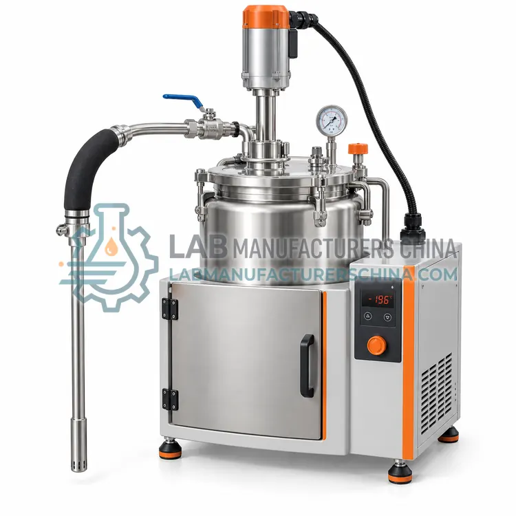
A cryogenic liquid transfer pump is a submerged-impeller or extended-shaft pump that moves liquid nitrogen at 5–50 L/min independent of source tank pressure. It is the right choice for high-volume or long-distance transfers, multi-dewar filling and pressure-limited source vessels.
What is the Cryogenic Liquid Transfer Pump?
A cryogenic liquid transfer pump is a submerged-impeller or extended-shaft pump that moves liquid nitrogen at 5–50 L/min independent of source tank pressure. It is the right choice for high-volume or long-distance transfers, multi-dewar filling and pressure-limited source vessels.
Overview
A transfer pump immerses its impeller or piston in the liquid, or uses an extended shaft from a warm motor, so the liquid cools the pump parts directly. Centrifugal designs deliver flow up to 50 L/min at differential pressures of 1 to 4 bar, and reciprocating piston designs reach higher pressure at lower flow. Stainless steel wetted parts and low-conductivity shafts limit heat input, and vapor return lines vent gas created during cool-down. The pump must be precooled, typically for 5 to 15 minutes, to avoid cavitation, and it should include a bypass or relief valve. Motors are sealed or explosion-protected depending on the environment. Pumps are used when a source tank has low pressure, when lines are long, or when many vessels must be filled quickly. Frequent use benefits from filters and preventive maintenance of seals and bearings.
How does it work?
Cryogenic transfer equipment reduces heat leak while liquid moves from a source vessel to a destination. Liquid is driven either by vessel pressure, by a self-pressurizing circuit that raises headspace pressure to about 0.5–1.5 bar, or by a cryogenic pump with a submerged or extended-shaft impeller. Vacuum-jacketed hoses and pipes suppress heat transfer with an evacuated annulus and multilayer insulation, so less liquid flashes to gas in the line. A phase separator placed at the outlet vents vapor through a float-operated valve so that only liquid flows to the receiving vessel, stabilizing filling. Auto-fill controllers combine level sensors, temperature sensors and solenoid valves that open when liquid is needed and close when level is reached, with timeout and fault alarms.
What are the key features?
- Submerged or extended-shaft impeller cools pump parts directly with the liquid.
- Flow up to 50 L/min independent of source tank pressure.
- Vapor return line handles gas generated during cool-down.
- Bypass and relief valves protect against blocked outlets.
- Stainless steel wetted parts with low-conductivity shafts.
- Sealed or explosion-protected motor options.
What are the technical specifications?
A typical cryogenic liquid transfer pump configuration offers flow rate of 5–50 L/min, differential pressure of 1–4 bar, pump type of Centrifugal or reciprocating, inlet/outlet connection of DN8–DN25, precool time of 5–15 min and motor power of 0.37–2.2 kW. Values are indicative of the product class; the exact figures for each configuration are confirmed on the quotation and the calibration documents supplied with the instrument.
Which applications is it used for?
The Cryogenic Liquid Transfer Pump is used in filling multiple dewars from bulk tanks, long-distance liquid nitrogen piping, supply to cryogenic storage systems and industrial cryogenic cooling. Across the wider Cryogenic Transfer Equipment class, laboratories also deploy it for filling dewars from bulk liquid nitrogen tanks, automatic refilling of cryogenic storage vessels and liquid nitrogen supply to cold traps and instruments.
Which standards and certifications apply?
Relevant standards and methods include ISO 21010, ISO 21009-1, EN 13458-2, GB/T 18442, EU Pressure Equipment Directive 2014/68/EU and EN 1252-1. Certification candidates for this model are CE, ISO 9001 manufacturing and ATEX motor option; each is to be confirmed for the specific configuration before shipment, and certificates are supplied only where they have been issued.
Cryogenic hoses and pipes must have pressure relief wherever liquid can be trapped between valves, since trapped liquid expanding on warming can rupture lines. Keep fittings clean and dry and avoid contamination with oil or grease, which is a hazard mostly with oxygen but good practice generally. Inspect hose outer braid and end fittings for damage, and test vacuum integrity of jacketed lines periodically. Operators should wear a face shield, cryogenic gloves and closed footwear, and work in ventilated rooms with oxygen monitors. Cool lines slowly to reduce thermal shock. Replace seals, gaskets and worn couplings on a schedule. Document calibration of level and temperature sensors on auto-fill systems and test alarm function regularly.
How do I select the right Cryogenic Liquid Transfer Pump?
Choose a pump when tank pressure is insufficient or flow requirements are high. For occasional dewar filling, a self-pressurizing vessel is simpler. In an RFQ, specify flow rate, differential pressure, line length, inlet and outlet connections, motor supply and any hazardous-area rating.
How does it compare with other Cryogenic Transfer Equipment variants?
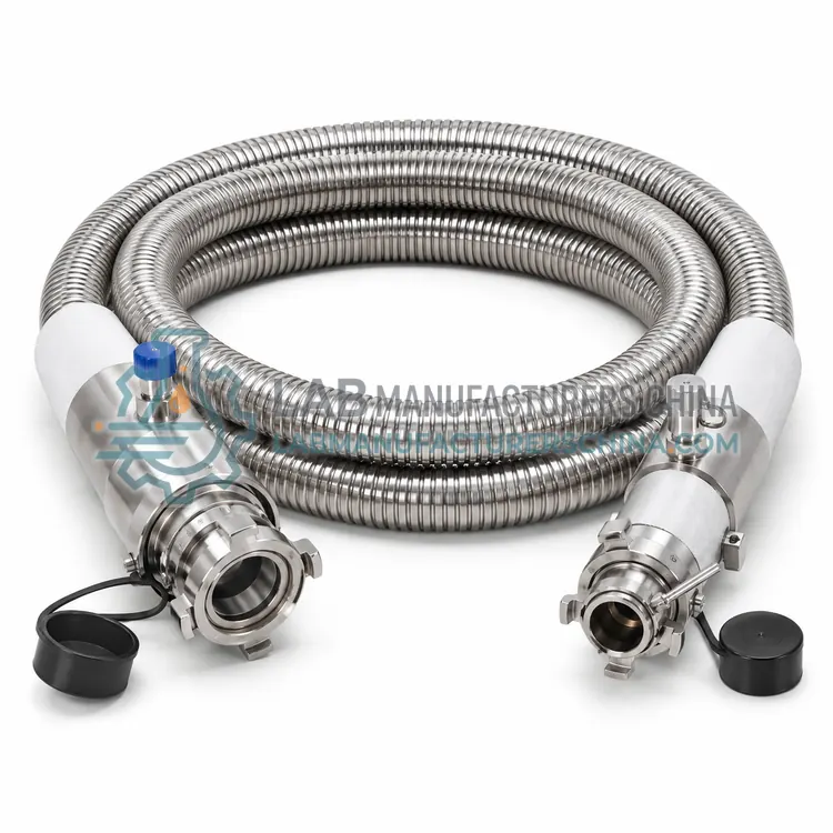
Match the equipment to the transfer task. For moving liquid from a bulk tank to dewars, choose a vacuum-jacketed hose with compatible fittings, pressure rating and a phase separator. For high-volume or long-distance transfer, consider a cryogenic pump, which works independently of tank pressure. For unattended filling of storage vessels, specify an auto-fill controller with level sensor, solenoid valve and alarms. For moving frozen samples within a facility, choose a transfer cart with vapor-phase capability and suitable dimensions for doors and lifts. Check hose length, bore, connection thread, maximum working pressure and temperature, material compatibility and whether a relief valve is included. Also consider operator safety features such as cold-resistant handles and splash shields.
Full specifications
| Flow rate | 5–50 L/min |
|---|---|
| Differential pressure | 1–4 bar |
| Pump type | Centrifugal or reciprocating |
| Inlet/outlet connection | DN8–DN25 |
| Precool time | 5–15 min |
| Motor power | 0.37–2.2 kW |
| Wetted materials | Stainless steel, PTFE seals |
| NPSH required | 0.3–1.0 m |
| Liquid temperature | −196°C |
| Power supply | 220/380 V AC, 50 Hz |
Indicative values for this product class. Final specifications are confirmed on the quotation and in the calibration documents supplied with the instrument.
Applications
- Filling multiple dewars from bulk tanks
- Long-distance liquid nitrogen piping
- Supply to cryogenic storage systems
- Industrial cryogenic cooling
Key features
- Submerged or extended-shaft impeller cools pump parts directly with the liquid.
- Flow up to 50 L/min independent of source tank pressure.
- Vapor return line handles gas generated during cool-down.
- Bypass and relief valves protect against blocked outlets.
- Stainless steel wetted parts with low-conductivity shafts.
- Sealed or explosion-protected motor options.
Frequently asked questions about Cryogenic Liquid Transfer Pump
If liquid nitrogen meets warm pump parts it boils, creating vapor that causes cavitation and loss of flow. Precooling lets the pump fill with liquid and reach stable temperature before the discharge valve is opened.
Usually yes, because gas produced during cool-down and from heat leak must escape. A return line to the source headspace or a vent prevents vapor lock and allows the pump to prime reliably.
Plan periodic inspection of seals, bearings and shaft alignment, typically every few hundred operating hours, plus cleaning of inlet strainers. Keep the pump dry between uses to prevent ice damage and record runtime in a maintenance log.
A phase separator is a small device at the end of a transfer line that vents nitrogen vapor while letting liquid pass. Because the line cools and flashes some liquid to gas, separating the phases gives a steadier flow and reduces splashing and liquid loss.
Liquid trapped between two closed valves warms and expands about 700 times as gas, which can burst pipes or hoses. A relief valve or burst disc between valve pairs prevents dangerous pressure and is required under pressure-equipment rules.
A pump is better when transfer volume is large, distance is long or the source tank has low pressure. It gives constant flow independent of tank pressure and reduces vapor loss, but costs more and needs precool and maintenance.