Handheld Optical Power Meter
手持式光功率计
- SKU OPM-0002
- Optical Power Meters
- CE (to be confirmed)
- ISO 9001 manufacturing (to be confirmed)
Price on request — FOB / CIF quoted per order
Prices depend on configuration, quantity and destination port.
Key specifications
| Wavelength range | 800–1700 nm |
|---|---|
| Calibrated wavelengths | 850, 1300, 1310, 1490, 1550, 1625 nm |
| Power range | −70 to +10 dBm |
| Accuracy | ±0.2 dB |
| Resolution | 0.01 dB |
| Detector | InGaAs photodiode |
Request a quote Download brochure · to be provided
By Lab Manufacturers China Technical TeamLast reviewed Standards: IEC 60825-1, ISO 11554, IEC 61315
What is the Handheld Optical Power Meter?
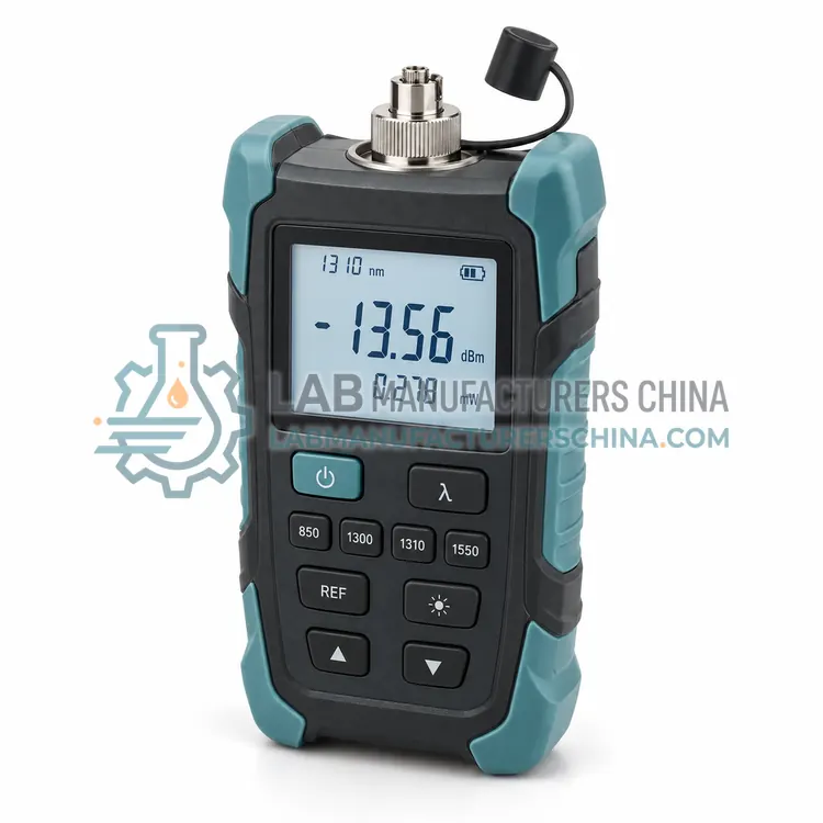
A handheld optical power meter is a compact, battery-powered instrument for measuring optical power in the field. It is widely used for fibre-optic installation, maintenance and troubleshooting where portability and quick readings matter.
What is the Handheld Optical Power Meter?
A handheld optical power meter is a compact, battery-powered instrument for measuring optical power in the field. It is widely used for fibre-optic installation, maintenance and troubleshooting where portability and quick readings matter.
Overview
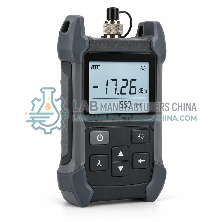
A handheld optical power meter houses a photodetector, calibrated wavelengths and a display in a palm-sized housing. Fibre is connected through an interchangeable adapter, and the meter reports absolute power in dBm or relative power in dB against a stored reference. Multiple calibrated wavelengths cover common fibre bands, and the user selects the one matching the source. Readings can be stored for later download, and a backlit display aids use in dim plant rooms. Rugged sealing and long battery life suit field work, while a reference mode supports loss measurement with a light source. Protective rubber boots and carry cases are common field accessories.
How does it work?
An optical power meter converts incident light into an electrical signal with a sensor whose spectral response is known. Photodiodes are fast and sensitive and suit low to moderate power; thermopiles absorb light and measure the resulting temperature rise for higher powers and broad wavelength coverage; pyroelectric sensors respond to pulsed energy. The signal is amplified, digitized and displayed in watts, dBm or relative units. Calibration against a traceable reference sets the responsivity, and the meter applies wavelength correction when the source differs from the calibration wavelength. Attenuators, integrating spheres and diffusers adapt the sensor to high power or divergent beams. Linearity, noise floor and response time define the usable measurement range.
What are the key features?
- Palm-sized battery-powered housing
- Multiple calibrated wavelengths for common fibre bands
- Absolute dBm and relative dB loss measurement
- Interchangeable fibre connectors
- Internal memory for stored readings
What are the technical specifications?
A typical handheld optical power meter configuration offers wavelength range of 800–1700 nm, calibrated wavelengths of 850, 1300, 1310, 1490, 1550, 1625 nm, power range of −70 to +10 dBm, accuracy of ±0.2 dB, resolution of 0.01 dB and detector of InGaAs photodiode. Values are indicative of the product class; the exact figures for each configuration are confirmed on the quotation and the calibration documents supplied with the instrument.
Which applications is it used for?
The Handheld Optical Power Meter is used in fibre-optic network installation, telecommunications maintenance, FTTH and data centre link testing and optical transmitter and receiver checks. Across the wider Optical Power Meters class, laboratories also deploy it for laser output power verification, fibre-optic link loss and attenuation testing and LED and display source characterization.
Which standards and certifications apply?
Relevant standards and methods include IEC 60825-1, ISO 11554, IEC 61315, ISO 13694 and IEC 61010-1. Certification candidates for this model are CE and ISO 9001 manufacturing; each is to be confirmed for the specific configuration before shipment, and certificates are supplied only where they have been issued.
Keep sensors clean and never exceed the specified maximum power or power density, which can damage the absorber permanently. Allow warm-up for stable readings and observe the recommended zeroing before low-level measurement. Calibration should be traceable and repeated at intervals defined by use and the quality system, typically annually. Follow laser safety requirements, including eye protection, beam enclosures and controlled areas, and mark the maximum permissible exposure for the setup. Store sensors with protective caps and document calibration certificates and corrections.
How do I select the right Handheld Optical Power Meter?
Select a handheld meter for field fibre testing where portability and speed matter. Confirm the calibrated wavelengths match the network sources, the power range covers expected levels, and the connectors suit the patch cords in use. A reference mode and a matching light source enable loss measurement. Check battery life, sealing and memory capacity for the working conditions.
How does it compare with other Optical Power Meters variants?
Start with the sensor type because it sets the power range, wavelength coverage and response time. Choose a photodiode meter for low-power, high-sensitivity work in the visible and near-infrared, a thermopile meter for medium to high laser power and broad wavelengths, and a pyroelectric meter for pulsed sources. For free-space beams, integrating spheres handle divergence and high power density; for fibre testing, choose a meter with the right connector and calibrated telecom wavelengths. Then confirm the required accuracy, resolution, wavelength correction range, display units and connectivity to records or control systems.
Full specifications
| Wavelength range | 800–1700 nm |
|---|---|
| Calibrated wavelengths | 850, 1300, 1310, 1490, 1550, 1625 nm |
| Power range | −70 to +10 dBm |
| Accuracy | ±0.2 dB |
| Resolution | 0.01 dB |
| Detector | InGaAs photodiode |
| Connector | FC, SC, ST interchangeable |
| Battery life | Over 100 h |
| Data storage | Up to 1,000 records |
| Data interface | USB |
Indicative values for this product class. Final specifications are confirmed on the quotation and in the calibration documents supplied with the instrument.
Applications
- Fibre-optic network installation
- Telecommunications maintenance
- FTTH and data centre link testing
- Optical transmitter and receiver checks
Key features
- Palm-sized battery-powered housing
- Multiple calibrated wavelengths for common fibre bands
- Absolute dBm and relative dB loss measurement
- Interchangeable fibre connectors
- Internal memory for stored readings
Frequently asked questions about Handheld Optical Power Meter
First measure a reference power through a short launch cable, store it as the reference, then measure through the link under test. The meter displays the difference in dB, which is the link loss. Using the same connectors and wavelengths for reference and test keeps the result reliable.
Optical networks use different wavelengths, such as 1310 nm and 1550 nm in telecommunications and 850 nm in short links. Detector responsivity varies with wavelength, so the meter applies the correct calibration for the selected wavelength to give an accurate dBm reading.
Keep the optical port and connector adapters clean, since dust causes large loss errors, and inspect and clean patch cords before connection. Replace batteries as indicated and verify calibration periodically against a reference source, typically once a year for professional use.
A photodiode sensor is fast and sensitive and suits low-power measurements over a limited wavelength range. A thermopile absorbs light and measures temperature rise, covering broad wavelengths and higher powers but with slower response. The choice depends on power level and response requirements.
Sensor responsivity varies with wavelength, so a meter calibrated at one wavelength can read incorrectly at another. Modern meters store a responsivity curve and apply a correction when the user enters the source wavelength. Using uncorrected readings introduces errors of several percent.
Use a sensor rated above the expected power and power density, attenuate or expand the beam if necessary, and follow IEC 60825-1 safety practice. Avoid direct viewing, control the beam path and use an integrating sphere for high-power or divergent beams to spread the energy.
Related models