Thermopile Laser Power Meter
热电堆激光功率计
- SKU OPM-0004
- Optical Power Meters
- CE (to be confirmed)
- ISO 9001 manufacturing (to be confirmed)
Price on request — FOB / CIF quoted per order
Prices depend on configuration, quantity and destination port.
Key specifications
| Power range | 10 mW to 200 W |
|---|---|
| Wavelength range | 190 nm to 20 µm |
| Aperture diameter | 25 mm |
| Accuracy | ±3% of reading |
| Response time | <2 s |
| Max power density | 10 kW/cm² |
Request a quote Download brochure · to be provided
By Lab Manufacturers China Technical TeamLast reviewed Standards: IEC 60825-1, ISO 11554, IEC 61315
What is the Thermopile Laser Power Meter?
A thermopile laser power meter measures medium to high laser power over a broad wavelength range by converting absorbed light into heat. It is used for CO₂, fibre, solid-state and other lasers where photodiodes would saturate or be damaged.
What is the Thermopile Laser Power Meter?
A thermopile laser power meter measures medium to high laser power over a broad wavelength range by converting absorbed light into heat. It is used for CO₂, fibre, solid-state and other lasers where photodiodes would saturate or be damaged.
Overview
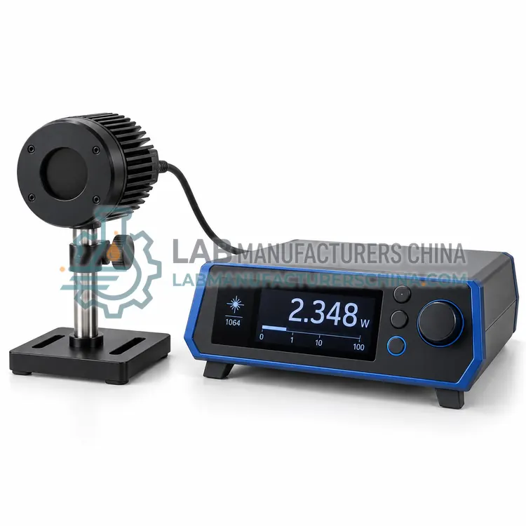
A thermopile laser power meter absorbs incident laser light in a broadband coating and measures the resulting temperature difference across a thermopile junction array. The voltage is proportional to absorbed power, so measurement is largely independent of wavelength when the coating is broadband. Absorbers are designed for high power density, and air or water cooling removes the heat for continuous use at high power. Response is slower than photodiodes but stable and linear over wide ranges. Aperture size and maximum power density must be matched to the beam, and the meter is used for absolute laser output measurement and process control.
How does it work?
An optical power meter converts incident light into an electrical signal with a sensor whose spectral response is known. Photodiodes are fast and sensitive and suit low to moderate power; thermopiles absorb light and measure the resulting temperature rise for higher powers and broad wavelength coverage; pyroelectric sensors respond to pulsed energy. The signal is amplified, digitized and displayed in watts, dBm or relative units. Calibration against a traceable reference sets the responsivity, and the meter applies wavelength correction when the source differs from the calibration wavelength. Attenuators, integrating spheres and diffusers adapt the sensor to high power or divergent beams. Linearity, noise floor and response time define the usable measurement range.
What are the key features?
- Broadband absorber coating for wide wavelength coverage
- Air or water cooling for high continuous power
- Aperture sized to the laser beam
- Linear response independent of wavelength
- Digital display with analogue and digital outputs
What are the technical specifications?
A typical thermopile laser power meter configuration offers power range of 10 mW to 200 W, wavelength range of 190 nm to 20 µm, aperture diameter of 25 mm, accuracy of ±3% of reading, response time of <2 s and max power density of 10 kW/cm². Values are indicative of the product class; the exact figures for each configuration are confirmed on the quotation and the calibration documents supplied with the instrument.
Which applications is it used for?
The Thermopile Laser Power Meter is used in high-power laser output measurement, industrial laser process monitoring, laser system calibration and service and research and material processing laboratories. Across the wider Optical Power Meters class, laboratories also deploy it for laser output power verification, fibre-optic link loss and attenuation testing and LED and display source characterization.
Which standards and certifications apply?
Relevant standards and methods include IEC 60825-1, ISO 11554, IEC 61315, ISO 13694 and IEC 61010-1. Certification candidates for this model are CE and ISO 9001 manufacturing; each is to be confirmed for the specific configuration before shipment, and certificates are supplied only where they have been issued.
Keep sensors clean and never exceed the specified maximum power or power density, which can damage the absorber permanently. Allow warm-up for stable readings and observe the recommended zeroing before low-level measurement. Calibration should be traceable and repeated at intervals defined by use and the quality system, typically annually. Follow laser safety requirements, including eye protection, beam enclosures and controlled areas, and mark the maximum permissible exposure for the setup. Store sensors with protective caps and document calibration certificates and corrections.
How do I select the right Thermopile Laser Power Meter?
Select a thermopile meter when laser power exceeds the range of photodiodes or when the wavelength varies. Match the maximum power and power density to the beam, and choose air or water cooling according to continuous duty. Confirm the aperture is large enough for the beam, and follow laser safety practice. Recalibration against a traceable standard is recommended at defined intervals.
How does it compare with other Optical Power Meters variants?
Start with the sensor type because it sets the power range, wavelength coverage and response time. Choose a photodiode meter for low-power, high-sensitivity work in the visible and near-infrared, a thermopile meter for medium to high laser power and broad wavelengths, and a pyroelectric meter for pulsed sources. For free-space beams, integrating spheres handle divergence and high power density; for fibre testing, choose a meter with the right connector and calibrated telecom wavelengths. Then confirm the required accuracy, resolution, wavelength correction range, display units and connectivity to records or control systems.
Full specifications
| Power range | 10 mW to 200 W |
|---|---|
| Wavelength range | 190 nm to 20 µm |
| Aperture diameter | 25 mm |
| Accuracy | ±3% of reading |
| Response time | <2 s |
| Max power density | 10 kW/cm² |
| Cooling | Air or water |
| Detector | Thermopile |
| Display | Digital LCD |
| Data interface | USB |
Indicative values for this product class. Final specifications are confirmed on the quotation and in the calibration documents supplied with the instrument.
Applications
- High-power laser output measurement
- Industrial laser process monitoring
- Laser system calibration and service
- Research and material processing laboratories
Key features
- Broadband absorber coating for wide wavelength coverage
- Air or water cooling for high continuous power
- Aperture sized to the laser beam
- Linear response independent of wavelength
- Digital display with analogue and digital outputs
Frequently asked questions about Thermopile Laser Power Meter
A thermopile responds to average power and is suitable for continuous or high-repetition lasers, but it is too slow to resolve individual pulses. For pulse energy and peak power, a pyroelectric energy meter is used. Choose the sensor according to whether average power or pulse energy is needed.
The absorber coating can be damaged if the power density exceeds its rating, changing responsivity or destroying the sensor. If the beam is small and intense, expand it or use an integrating sphere. Always check the specified maximum power density for the sensor and beam diameter.
Annual calibration is typical for laboratory and production use, or more frequent where accuracy is critical or the sensor experiences high power. Calibration against a traceable reference confirms responsivity, and certificates should be retained as part of the measurement record.
A photodiode sensor is fast and sensitive and suits low-power measurements over a limited wavelength range. A thermopile absorbs light and measures temperature rise, covering broad wavelengths and higher powers but with slower response. The choice depends on power level and response requirements.
Sensor responsivity varies with wavelength, so a meter calibrated at one wavelength can read incorrectly at another. Modern meters store a responsivity curve and apply a correction when the user enters the source wavelength. Using uncorrected readings introduces errors of several percent.
Use a sensor rated above the expected power and power density, attenuate or expand the beam if necessary, and follow IEC 60825-1 safety practice. Avoid direct viewing, control the beam path and use an integrating sphere for high-power or divergent beams to spread the energy.
Related models