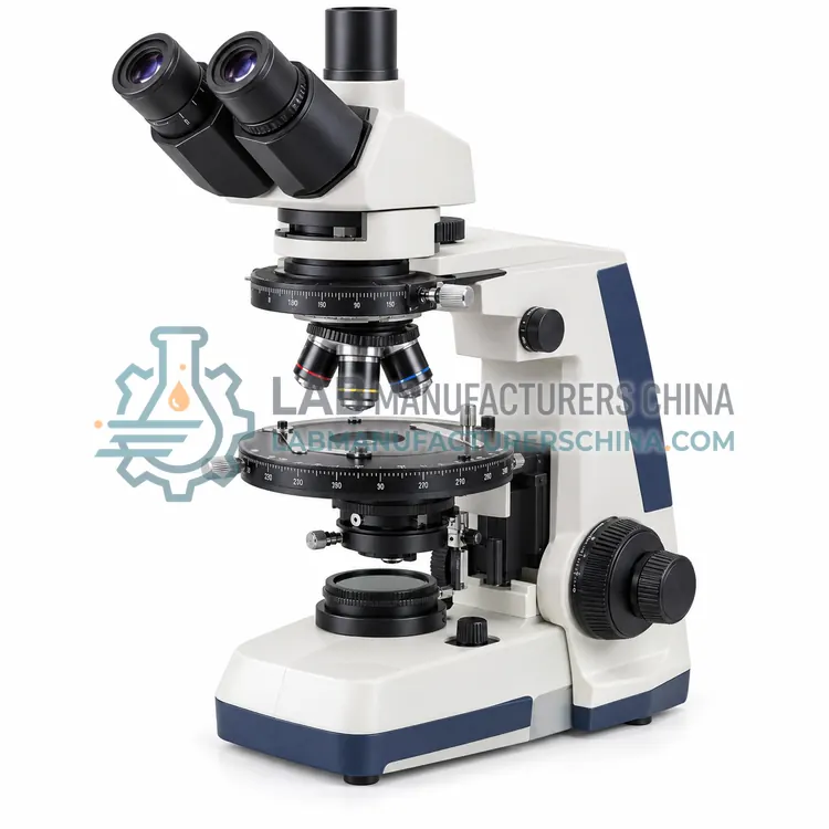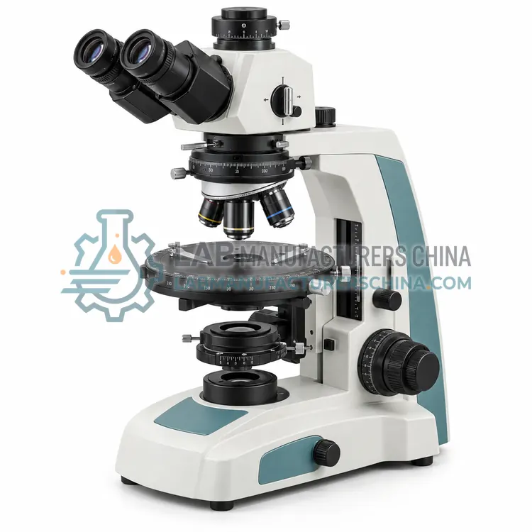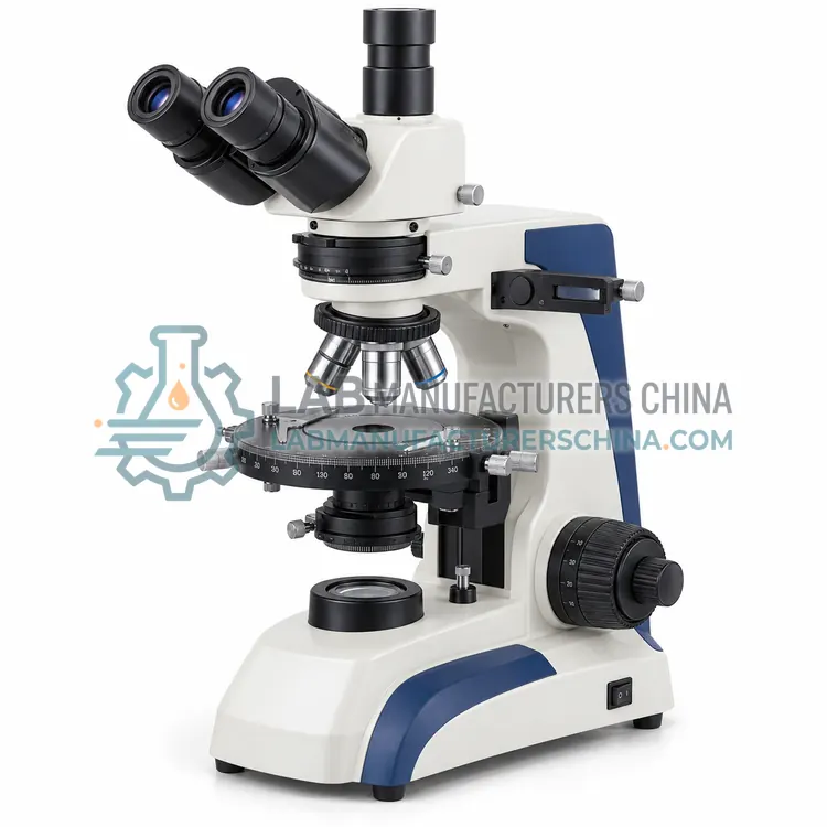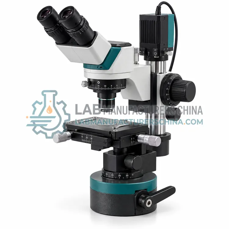
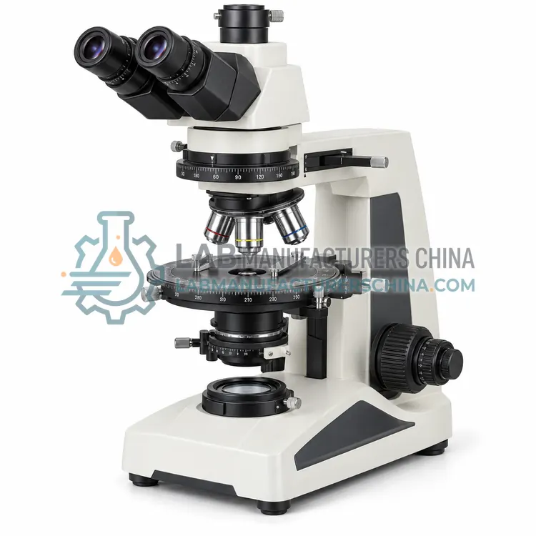
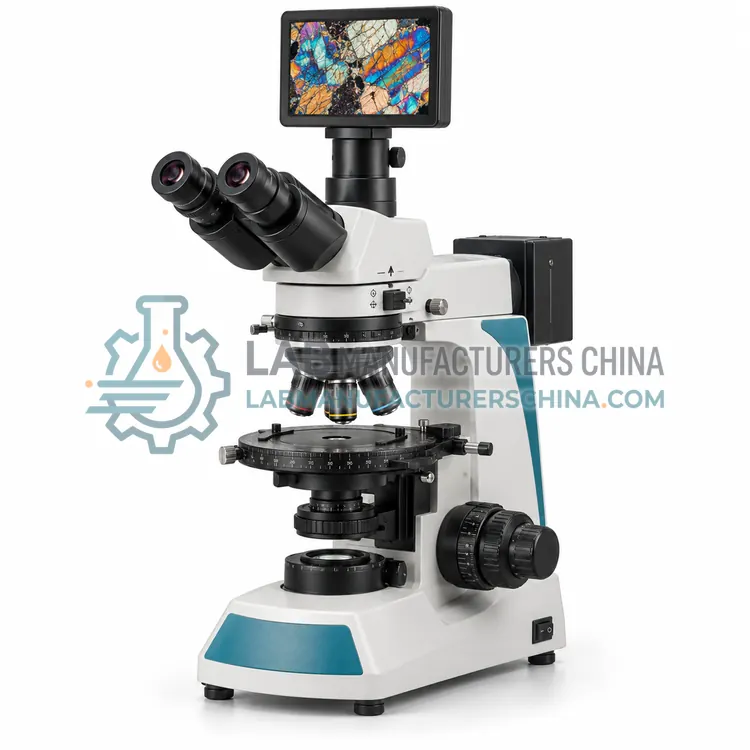
Digital Polarizing Microscope
数字偏光显微镜
- SKU POM-0004
- Polarizing Microscopes
- CE (to be confirmed)
- ISO 9001 manufacturing (to be confirmed)
Price on request — FOB / CIF quoted per order
Prices depend on configuration, quantity and destination port.
Key specifications
| Optical system | Infinite corrected, strain-free |
|---|---|
| Magnification range | 40×–600× |
| Objectives | 4×, 10×, 40×, 60× strain-free |
| Camera resolution | 5–20 MP |
| Stage | Rotating 360°, graduated 1° |
| Polarizers | Polarizer and analyser, crossed |
Request a quote Download brochure · to be provided
By Lab Manufacturers China Technical TeamLast reviewed Standards: ISO 8036, ISO 19012-1, ASTM E3
What is the Digital Polarizing Microscope?
A digital polarizing microscope captures polarized-light images through a digital camera and analyzes them with software. It combines anisotropy observation with measurement, annotation and archival of results. Recording of stage angle and polarization state supports reproducibility.
What is the Digital Polarizing Microscope?
A digital polarizing microscope captures polarized-light images through a digital camera and analyzes them with software. It combines anisotropy observation with measurement, annotation and archival of results. Recording of stage angle and polarization state supports reproducibility.
Overview
A digital polarizing microscope retains the polarizer, analyser, rotating stage and strain-free optics of a conventional instrument but adds a high-resolution camera and software. Images are displayed on a monitor, captured at selected stage angles and analyzed for interference colours, retardation and grain boundaries. Software can measure lengths, angles and areas after calibration, and can compare images or build mosaics. Digital capture eases documentation and reporting and supports teaching and remote review. The rotating stage and polarizer settings must be recorded with each image so the polarization state is known. Colour accuracy of the camera and display requires attention for colour-based analysis.
How does it work?
A polarizing microscope places a polarizer below the specimen and an analyser above it, usually with their transmission directions crossed. Isotropic materials appear dark under crossed polarizers, while anisotropic materials split light into two rays and change its polarization, producing interference colours and extinction positions as the stage rotates. With a full-wave plate and accessory plates, retardation and optical sign can be estimated, and conoscopic observation with a Bertrand lens shows interference figures that identify crystal systems and optic axes. A rotating, centred stage with graduated scale allows precise angle measurement. Polarized light therefore converts differences in crystal orientation and refractive index into visible colours and extinction behaviour.
What are the key features?
- Digital camera with monitor display
- Software for capture, measurement and annotation
- Recording of stage angle and polarization settings
- Image mosaics and comparison functions
- Suitable for teaching and remote review
What are the technical specifications?
A typical digital polarizing microscope configuration offers optical system of Infinite corrected, strain-free, magnification range of 40×–600×, objectives of 4×, 10×, 40×, 60× strain-free, camera resolution of 5–20 MP, stage of Rotating 360°, graduated 1° and polarizers of Polarizer and analyser, crossed. Values are indicative of the product class; the exact figures for each configuration are confirmed on the quotation and the calibration documents supplied with the instrument.
Which applications is it used for?
The Digital Polarizing Microscope is used in automated mineral and crystal measurement, teaching with projected images, documented polymorphism screening and fibre and polymer orientation analysis. Across the wider Polarizing Microscopes class, laboratories also deploy it for mineral and rock identification, crystal and pharmaceutical polymorph study and fibre and polymer orientation analysis.
Which standards and certifications apply?
Relevant standards and methods include ISO 8036, ISO 19012-1, ASTM E3, ISO 7404-3 and IEC 61010-1. Certification candidates for this model are CE and ISO 9001 manufacturing; each is to be confirmed for the specific configuration before shipment, and certificates are supplied only where they have been issued.
Centre and focus the rotating stage so the specimen stays in view, and calibrate the crosshair and scale against a known reference before measuring angles. Use strain-free objectives and keep polarizer and analyser clean; strain in optics or contamination produces false colours and extinction. Set the analyser accurately to extinction with no specimen in place. For quantitative retardation work, verify accessory plates and compensators and record their orientation. Avoid heat and vibration, which disturb optical alignment, and store the microscope with accessories protected. Recalibrate after service.
How do I select the right Digital Polarizing Microscope?
Choose a digital polarizing microscope when images must be captured, measured or shared. Confirm camera resolution and colour fidelity suit colour-based analysis, and that software supports calibration, angle measurement and record keeping. Ensure stage angle and polarization settings can be recorded with images for reproducibility.
How does it compare with other Polarizing Microscopes variants?
Choose a polarizing microscope when optical anisotropy must be studied, such as identifying minerals, crystals, fibres or polymer structure. Decide whether transmitted polarized light is sufficient or whether reflected polarized light is also needed for opaque ores and polished sections. Confirm the stage rotates and is centred, and that a graduated scale with vernier is present for angle measurement. Consider whether strain-free objectives, a Bertrand lens, accessory plates and a conoscopic path are required. For quantitative work, a compensator and calibrated plates may be needed. Digital models add imaging and measurement software.
Full specifications
| Optical system | Infinite corrected, strain-free |
|---|---|
| Magnification range | 40×–600× |
| Objectives | 4×, 10×, 40×, 60× strain-free |
| Camera resolution | 5–20 MP |
| Stage | Rotating 360°, graduated 1° |
| Polarizers | Polarizer and analyser, crossed |
| Display output | HDMI and USB |
| Software | Measurement and image analysis |
| Illumination | Transmitted, LED |
| Power supply | 100–240 V AC |
Indicative values for this product class. Final specifications are confirmed on the quotation and in the calibration documents supplied with the instrument.
Applications
- Automated mineral and crystal measurement
- Teaching with projected images
- Documented polymorphism screening
- Fibre and polymer orientation analysis
Key features
- Digital camera with monitor display
- Software for capture, measurement and annotation
- Recording of stage angle and polarization settings
- Image mosaics and comparison functions
- Suitable for teaching and remote review
Frequently asked questions about Digital Polarizing Microscope
Software can analyse colour and estimate retardation if the camera colour response and illumination are calibrated and the specimen thickness is known. However, colour reproduction depends on the whole optical and display chain, so automatic results should be verified against visual observation and reference plates.
Record the objective and magnification, the stage rotation angle, the polarizer and analyser settings, whether accessory plates were used, the illumination and the calibration scale. These parameters define the polarization state and make the image comparable and reproducible.
Yes. Projecting the image on a monitor lets groups observe the same view, and software can annotate extinction positions and interference figures. Recorded images also let students compare results and study structures outside the laboratory session.
Birefringence is the property of anisotropic materials to split a light ray into two rays that travel at different speeds and have different refractive indices. Under crossed polarizers it produces interference colours and characteristic extinction as the specimen rotates, which helps identify and study such materials.
Rotating the stage changes the orientation of the specimen relative to the polarizers, so the extinction positions and interference colours can be observed and measured. The graduated scale and vernier let the extinction angle be read and compared with reference data for identification.
Orthoscopic observation uses parallel light to form a normal image of the specimen, showing interference colours and extinction. Conoscopic observation inserts a Bertrand lens to converge the light and form an interference figure in the back focal plane, revealing optic axes and helping determine the crystal system.
Related models