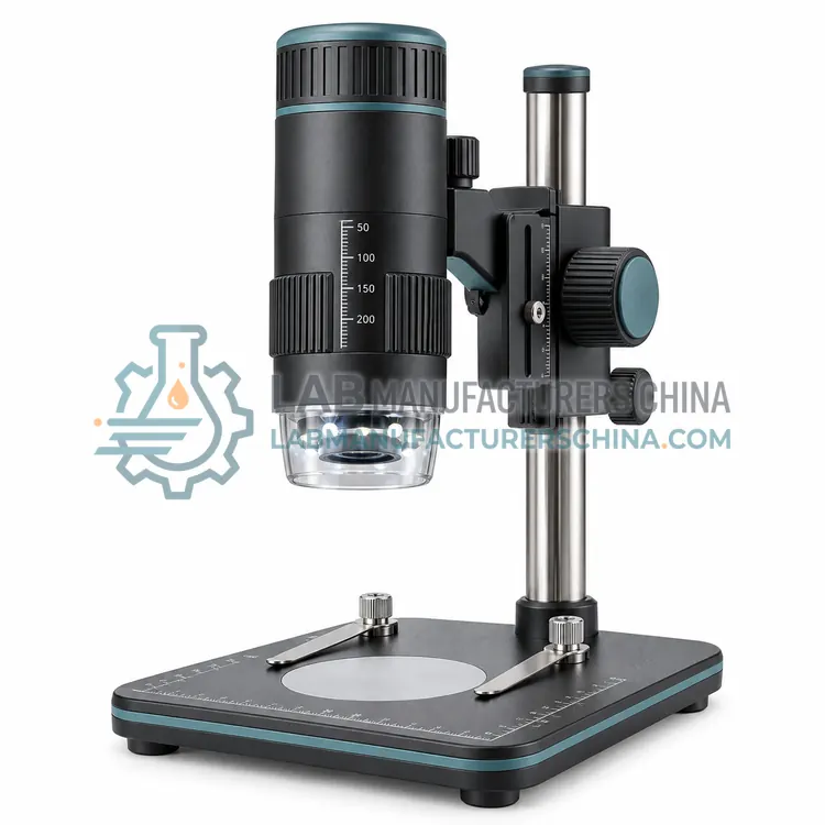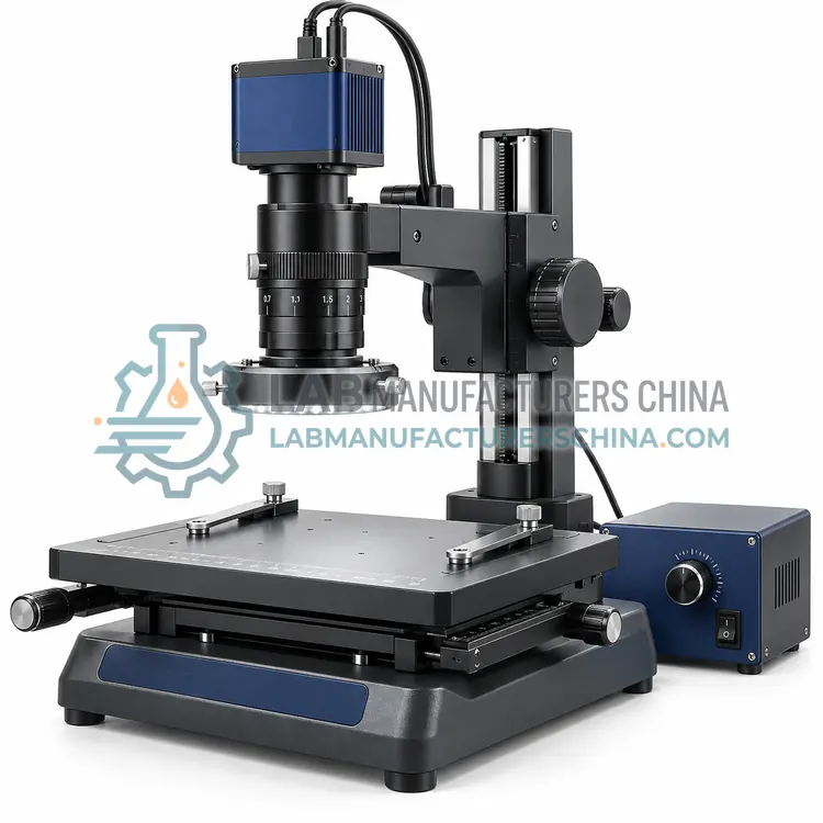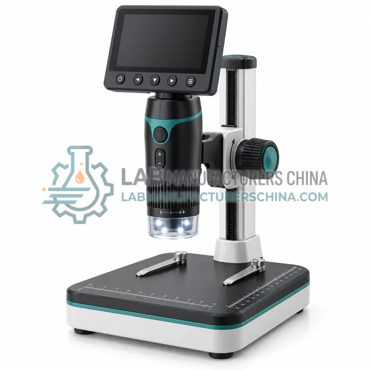
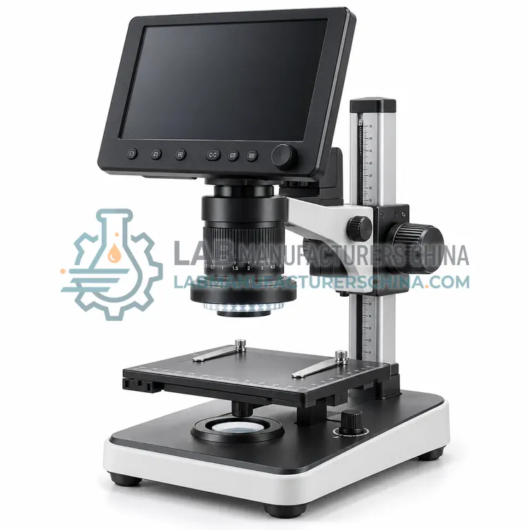
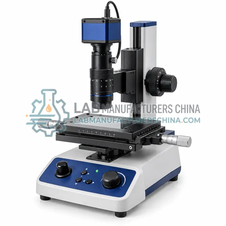
Measuring Digital Microscope
测量数字显微镜
- SKU DIM-0005
- Digital Microscopes
- CE (to be confirmed)
- ISO 9001 manufacturing (to be confirmed)
Price on request — FOB / CIF quoted per order
Prices depend on configuration, quantity and destination port.
Key specifications
| Magnification range | 20×–300× on screen |
|---|---|
| Image sensor | 5–20 MP CMOS |
| Measuring accuracy | ±0.01 mm with calibration |
| Field of view | About 20 mm at low magnification |
| Working distance | About 100 mm, fixed by stand |
| Measurement tools | Distance, angle, radius, area |
Request a quote Download brochure · to be provided
By Lab Manufacturers China Technical TeamLast reviewed Standards: ISO 8036, ISO 19012-1, ISO 9345-1
What is the Measuring Digital Microscope?
A measuring digital microscope combines digital imaging with calibrated measurement tools for dimensions, angles and areas. It is used where inspection requires quantitative results rather than visual assessment alone in production and quality control.
What is the Measuring Digital Microscope?
A measuring digital microscope combines digital imaging with calibrated measurement tools for dimensions, angles and areas. It is used where inspection requires quantitative results rather than visual assessment alone in production and quality control.
Overview
A measuring digital microscope adds precise calibration and measurement functions to digital imaging. After imaging a stage micrometer or certified target, the software relates pixels to real length, and operators measure distances, angles, radii and areas on the live or stored image. Overlays, tolerances and reports support quality decisions, and multiple measurement tools allow feature comparison against drawings. A stable stand and consistent working distance keep magnification constant so calibration remains valid, and illumination is controlled to give repeatable edges, especially on reflective parts. The instrument suits incoming inspection, tool verification and production metrology at magnifications where a video measuring system or comparator would be over-specified.
How does it work?
A digital microscope forms a magnified image with a lens system, then projects it onto an image sensor instead of an eyepiece. The sensor converts the optical image into digital data, which a processor displays on an LCD panel, a computer monitor or a mobile device. Image processing adjusts exposure, white balance, contrast and edge enhancement, and software overlays scales and markers. Magnification results from the optical magnification and the sensor and display dimensions, so the field of view and displayed magnification must be stated carefully. Illumination, often ring or coaxial LED, controls reflectance and reveals surface detail. Digital capture enables measurement, annotation, archiving and sharing, but measurement requires calibration against a known reference.
What are the key features?
- Calibrated measurement of distance, angle and area
- Tolerance overlays and pass or fail reporting
- Multiple measurement tools on live and stored images
- Stable stand keeping magnification constant
- Controlled illumination for repeatable edges
What are the technical specifications?
A typical measuring digital microscope configuration offers magnification range of 20×–300× on screen, image sensor of 5–20 MP CMOS, measuring accuracy of ±0.01 mm with calibration, field of view of About 20 mm at low magnification, working distance of About 100 mm, fixed by stand and measurement tools of Distance, angle, radius, area. Values are indicative of the product class; the exact figures for each configuration are confirmed on the quotation and the calibration documents supplied with the instrument.
Which applications is it used for?
The Measuring Digital Microscope is used in incoming and outgoing goods inspection, tool and die verification, defect size measurement and small-part dimensional metrology. Across the wider Digital Microscopes class, laboratories also deploy it for industrial surface and component inspection, electronics and PCB quality control and teaching with shared images.
Which standards and certifications apply?
Relevant standards and methods include ISO 8036, ISO 19012-1, ISO 9345-1, ISO 8255-1 and IEC 61010-1. Certification candidates for this model are CE and ISO 9001 manufacturing; each is to be confirmed for the specific configuration before shipment, and certificates are supplied only where they have been issued.
Calibrate the measurement scale with a stage micrometer or certified target, and recalibrate whenever the lens, working distance or display settings change. Keep the lens and sensor window clean, and control glare from reflective surfaces with diffused or polarised illumination. Set consistent illumination, white balance and exposure so images can be compared across sessions. Store calibration data and images with the settings recorded. For regulated inspection, ensure files are protected and traceable, and define user access and backup. Check that the stated magnification refers to the display and is reproducible.
How do I select the right Measuring Digital Microscope?
Choose a measuring digital microscope when quantitative dimensions, angles or defect sizes are required. Confirm the calibrated accuracy meets the tolerance, that the stand holds the working distance constant, and that the software supports the required tools, tolerances and reports. Ensure certified calibration targets are available and that the system is recalibrated on a defined schedule.
How does it compare with other Digital Microscopes variants?
Choose a digital microscope when image capture, measurement or documentation is central, or when eyepiece viewing is impractical. Decide the display route: an integrated LCD for standalone use, USB to a computer, HDMI to a monitor or wireless to a tablet. Confirm the optical magnification range and the numerical aperture, since sensor magnification does not add optical detail. Check the illumination type for the surface, the working distance for the task, and whether measurement software with calibration is included. For inspection lines, consider depth of field, field of view and the ability to record pass or fail results.
Full specifications
| Magnification range | 20×–300× on screen |
|---|---|
| Image sensor | 5–20 MP CMOS |
| Measuring accuracy | ±0.01 mm with calibration |
| Field of view | About 20 mm at low magnification |
| Working distance | About 100 mm, fixed by stand |
| Measurement tools | Distance, angle, radius, area |
| Tolerance function | Pass or fail overlays |
| Illumination | Adjustable LED with diffuser |
| Output | HDMI, USB, or network |
| Power supply | 12 V DC adapter |
Indicative values for this product class. Final specifications are confirmed on the quotation and in the calibration documents supplied with the instrument.
Applications
- Incoming and outgoing goods inspection
- Tool and die verification
- Defect size measurement
- Small-part dimensional metrology
Key features
- Calibrated measurement of distance, angle and area
- Tolerance overlays and pass or fail reporting
- Multiple measurement tools on live and stored images
- Stable stand keeping magnification constant
- Controlled illumination for repeatable edges
Frequently asked questions about Measuring Digital Microscope
With calibration against a certified target, accuracy on the order of tens of micrometres is achievable, but the result depends on edge definition, illumination, magnification and the calibration itself. The measurement uncertainty should be established and stated against the tolerance required.
Changing the working distance changes the magnification and therefore the pixel scale, which invalidates the calibration. A fixed stand and lens setting, or a telecentric lens, keeps magnification constant so that stored calibrations remain valid across sessions.
Yes, most measuring systems can export images with overlays, measurement lists and tolerances to a file or report, and some integrate with quality systems. Confirm the export formats and whether records include calibration data for traceability.
No. Resolution is set by the optical system, mainly the numerical aperture and wavelength, and by the sensor pixel density. Enlarging a digital image beyond the optical limit produces an empty, blurred result. Optical magnification and sensor resolution must be balanced.
Image a stage micrometer or certified target at the same optical and display settings used for measurement, then set the scale in the software so that pixels correspond to a known length. Recalibrate whenever the lens, working distance or display configuration changes.
Coaxial or diffuse illumination often suits reflective metals better than a ring light, because it reduces hot spots. Polarising filters can further suppress glare. For textured surfaces, oblique lighting increases contrast by creating shadows that reveal relief.
Related models