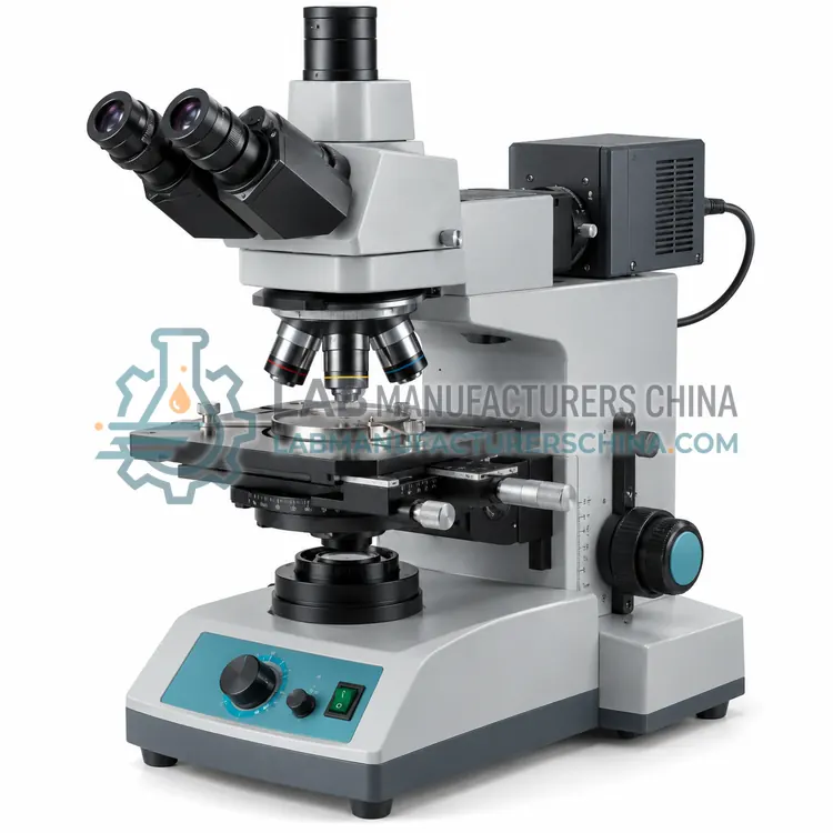
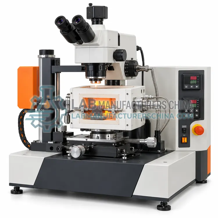
Digital Vision Measuring Microscope
数字影像测量显微镜
- SKU MIP-0003
- Microscopy
- CE (to be confirmed)
- ISO 9001 manufacturing (to be confirmed)
Price on request — FOB / CIF quoted per order
Prices depend on configuration, quantity and destination port.
Key specifications
| Measurement range | 200 × 150 mm typical stage |
|---|---|
| Magnification | 0.5× to 5× optical, digital zoom optional |
| Length accuracy | About ± (3 + L/100) µm typical |
| Repeatability | 1–3 µm depending on optics |
| Camera | 5–20 megapixels, monochrome or colour |
| Z axis | Motorized with focus detection |
Request a quote Download brochure · to be provided
By Lab Manufacturers China Technical TeamLast reviewed Standards: ASTM E3, ASTM E407, ASTM E112
What is the Digital Vision Measuring Microscope?
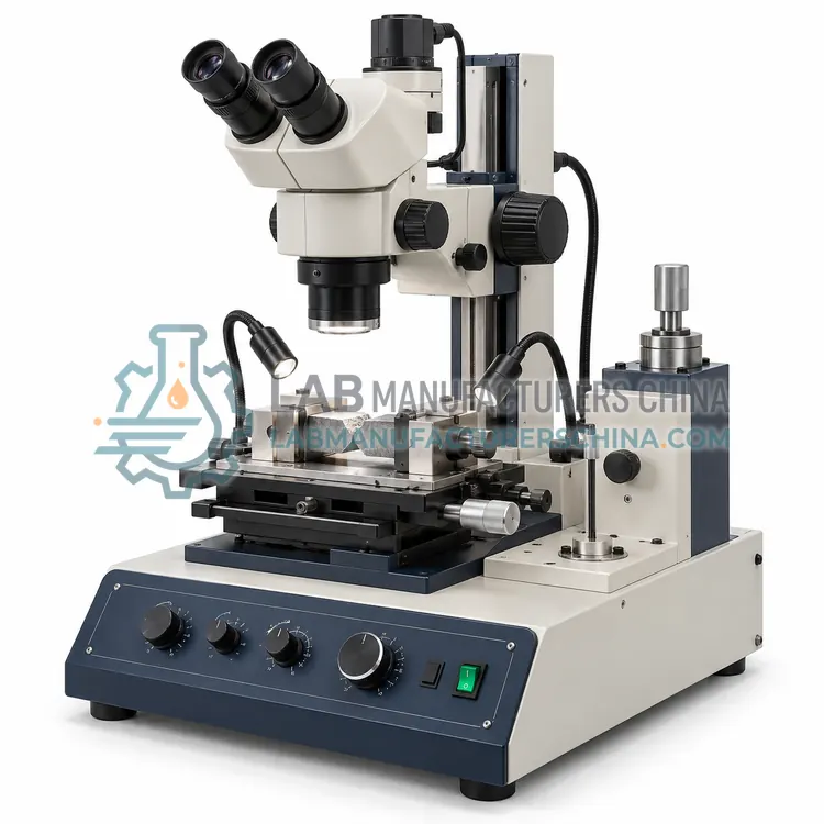
A digital vision measuring microscope combines optics with a calibrated camera and software to measure dimensions on small parts, tool edges, holes and coating cross-sections. It reports coordinates and lengths with documented accuracy.
What is the Digital Vision Measuring Microscope?
A digital vision measuring microscope combines optics with a calibrated camera and software to measure dimensions on small parts, tool edges, holes and coating cross-sections. It reports coordinates and lengths with documented accuracy.
Overview
The system images the specimen on a large sensor and software detects edges, allowing lengths, angles, radii and hole diameters to be measured on screen. Telecentric optics keep magnification constant across the field so measurements do not depend on focus, and a motorized XY stage with a Z axis allows coordinates to be captured over a defined area or a stitched image to be built for large parts. Calibration with a certified glass scale or grid artefact is fundamental: accuracy claims, resolution and repeatability must be checked against the artefact and re-verified after any change of lens, camera or software. Illumination options include coaxial, ring and backlight to suit different edges, and measuring routines can be saved so that the same feature is measured identically on each batch. Typical use is dimensional inspection of small metal parts, inserts, dies and coated sections.
How does it work?
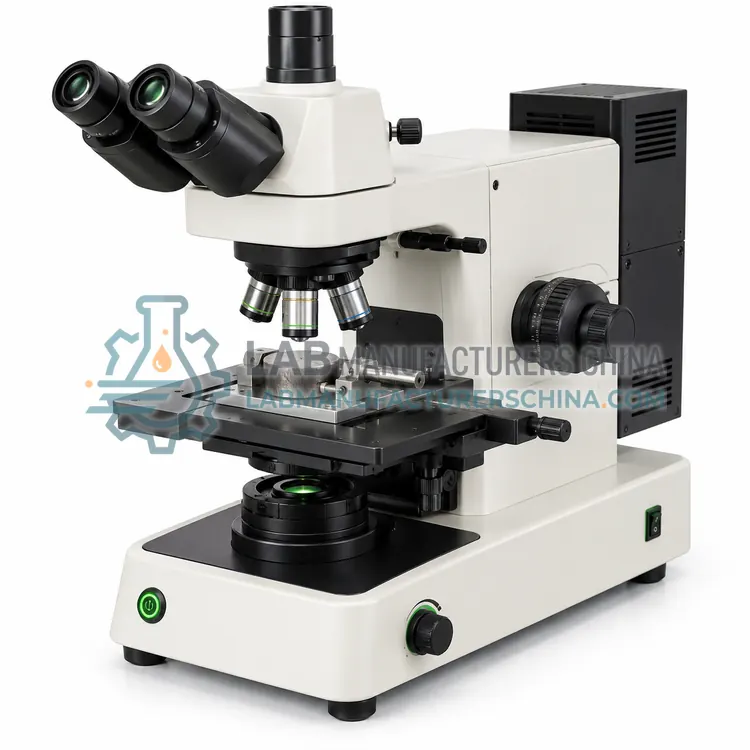
A metallurgical microscope illuminates the specimen from the same side as the objective, since metal is opaque, and the polished and etched surface reflects light back through the optical system. Contrast comes from differences in reflectivity between phases, from surface relief created by etching, and from scattering by inclusions and cracks. Objective numerical aperture determines resolution, and magnification should be chosen so that the features of interest occupy a reasonable fraction of the field, because empty magnification adds no detail. Illumination modes extend the range: brightfield for general structure, darkfield for inclusions and cracks, polarized light for anisotropic phases and coatings, and differential interference contrast for relief and small height differences. Stereo microscopes use separate light paths for each eye to give depth perception, which makes them suitable for fracture surfaces and weld profiles. Digital cameras and measuring software add quantitative output, such as grain size, coating thickness and defect dimensions.
What are the key features?
- Telecentric optics for constant magnification
- High resolution camera with edge detection software
- Motorized XY stage with Z axis and stitching option
- Coaxial, ring and backlight illumination
- Calibration with certified grid or glass scale
- Saved measuring routines for repeat measurements
What are the technical specifications?
A typical digital vision measuring microscope configuration offers measurement range of 200 × 150 mm typical stage, magnification of 0.5× to 5× optical, digital zoom optional, length accuracy of About ± (3 + L/100) µm typical, repeatability of 1–3 µm depending on optics, camera of 5–20 megapixels, monochrome or colour and Z axis of Motorized with focus detection. Values are indicative of the product class; the exact figures for each configuration are confirmed on the quotation and the calibration documents supplied with the instrument.
Which applications is it used for?
The Digital Vision Measuring Microscope is used in dimensional inspection of small metal parts, tool edge, die and insert measurement, coating and layer thickness on cross-sections and hole, thread and profile measurement. Across the wider Microscopy class, laboratories also deploy it for grain size and inclusion rating of steels, weld and heat-affected zone examination and fracture surface and failure investigation.
Which standards and certifications apply?
Relevant standards and methods include ASTM E3, ASTM E407, ASTM E112, ASTM E45, ISO 643, ASTM E1951 and IEC 61010-1. Certification candidates for this model are CE and ISO 9001 manufacturing; each is to be confirmed for the specific configuration before shipment, and certificates are supplied only where they have been issued.
Clean lenses only with the recommended method, since immersion oils and abrasives damage coatings, and cover the instrument when not in use. Verify magnification and length calibration with a stage micrometer at each objective and after any change of camera or software, and keep a record with the results. Set illumination to a reproducible level, because contrast in reflected light depends strongly on lamp intensity and aperture settings, and note the objective and illumination mode in every report. Keep specimens clean and dry, store them in labelled containers, and use replicas rather than marking the component when examining installed parts. Service the illuminator, stage and focusing mechanism periodically, and check the camera sensor for dust that would appear as artefacts in images used for measurement, since a mistaken artefact can change a reported coating thickness.
How do I select the right Digital Vision Measuring Microscope?
Select the vision measuring microscope when dimensional accuracy must be documented and repetitive, and check the accuracy specification against your tightest tolerance. Specify measuring range, optics, lighting, calibration artefact and the software functions you need for reporting.
How does it compare with other Microscopy variants?
Choose the microscope type from what must be seen. Upright reflected-light instruments with a full objective set and multiple illumination modes handle polished sections, grain size and inclusion rating. Inverted stages are better for large or unmounted specimens. Stereo microscopes are the right tool for fracture surfaces, weld profiles, corrosion damage and assembly inspection, where depth and surface shape matter more than high magnification. Digital measuring microscopes suit dimensional work on small features, such as tool edges, holes, threads and coating cross-sections, where accuracy claims need to be supported by calibration. Portable microscopes serve on-site replica examination of installed plant. In every case, match the magnification range, numerical aperture and illumination modes to the features of interest, and budget for a stage micrometer, calibration slides and a camera whose resolution genuinely exceeds the detail the optics can deliver.
Full specifications
| Measurement range | 200 × 150 mm typical stage |
|---|---|
| Magnification | 0.5× to 5× optical, digital zoom optional |
| Length accuracy | About ± (3 + L/100) µm typical |
| Repeatability | 1–3 µm depending on optics |
| Camera | 5–20 megapixels, monochrome or colour |
| Z axis | Motorized with focus detection |
| Calibration artefact | Certified grid or glass scale |
| Power supply | 220 V, 50/60 Hz |
Indicative values for this product class. Final specifications are confirmed on the quotation and in the calibration documents supplied with the instrument.
Applications
- Dimensional inspection of small metal parts
- Tool edge, die and insert measurement
- Coating and layer thickness on cross-sections
- Hole, thread and profile measurement
Key features
- Telecentric optics for constant magnification
- High resolution camera with edge detection software
- Motorized XY stage with Z axis and stitching option
- Coaxial, ring and backlight illumination
- Calibration with certified grid or glass scale
- Saved measuring routines for repeat measurements
Frequently asked questions about Digital Vision Measuring Microscope
They keep magnification constant regardless of distance, so parts of the specimen at different heights still measure the same size. This removes the parallax error that affects ordinary lenses.
By measuring a certified grid or glass scale of known dimensions over the working range and comparing the readings with the stated values, with the result recorded and repeated after any change to optics, camera or software.
Backlight produces a silhouette that gives the sharpest edge definition for through-features such as holes and profiles, while coaxial light suits flat reflective surfaces and ring light suits surfaces with relief or texture.
Metals are opaque, so transmitted illumination cannot pass through a polished section. Light is directed through the objective onto the specimen and reflected back, and contrast comes from differences in reflectivity and from surface relief.
Darkfield, because inclusions and voids scatter light and appear bright against a dark background, whereas they can be nearly invisible in brightfield if their reflectivity is similar to the matrix.
For fracture surfaces, weld profiles, corrosion pits and assembled parts, where three-dimensional shape and depth are important and high magnification with a polished, flat surface is not applicable.
Related models