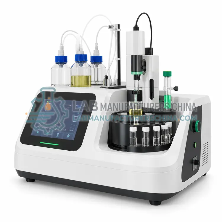
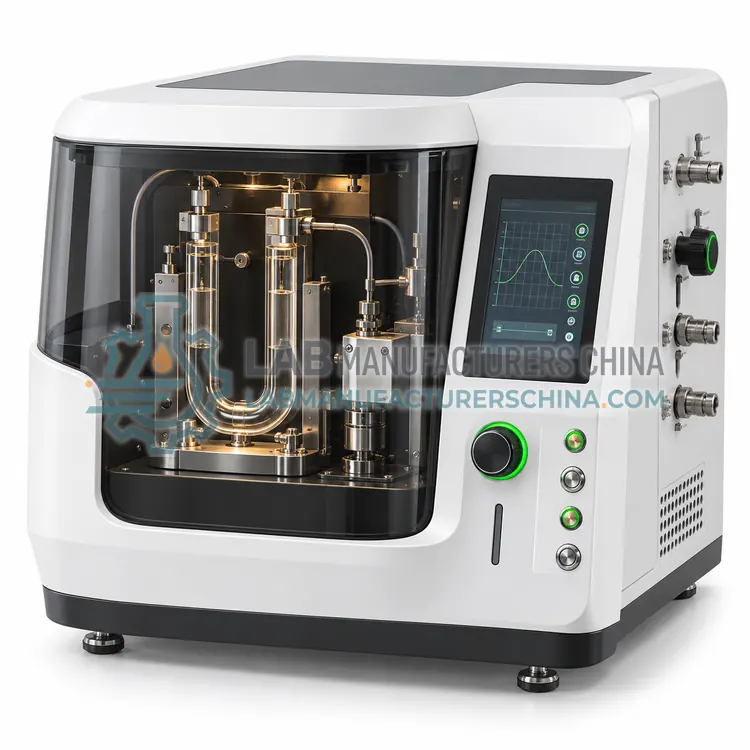
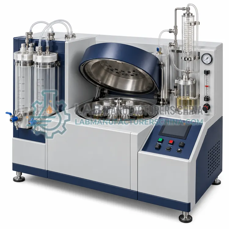
Water and Sediment Centrifuge for Fuel Oil
燃料油水分沉淀物离心机
- SKU FOA-0005
- Fuel Oil Analysis
- CE (to be confirmed)
- ISO 9001 manufacturing (to be confirmed)
Price on request — FOB / CIF quoted per order
Prices depend on configuration, quantity and destination port.
Key specifications
| Number of tubes | 4, 6 or 8 × 100 mL |
|---|---|
| Relative centrifugal force | ≥ 800 at tip (up to 1500) |
| Speed range | 500–4000 rpm |
| Temperature control | Ambient to 65 °C, ± 3 °C |
| Timer | 1–99 min |
| Tube readability | 0.05 mL (0–1 mL), 0.1 mL beyond |
Request a quote Download brochure · to be provided
By Lab Manufacturers China Technical TeamLast reviewed Standards: ISO 8217, ASTM D396, ASTM D4052
What is the Water and Sediment Centrifuge for Fuel Oil?
A water and sediment centrifuge spins fuel oil mixed with solvent and demulsifier in graduated tubes to separate free water and sediment, which are read directly as volume percent. It is used at terminals, refineries and ships for acceptance and quantity adjustment.
What is the Water and Sediment Centrifuge for Fuel Oil?
A water and sediment centrifuge spins fuel oil mixed with solvent and demulsifier in graduated tubes to separate free water and sediment, which are read directly as volume percent. It is used at terminals, refineries and ships for acceptance and quantity adjustment.
Overview
Equal volumes of fuel and water-saturated toluene, plus a demulsifier solution, are placed in 100 mL cone-shaped centrifuge tubes, mixed, and heated in a bath at 60 degrees Celsius. The tubes are then spun at a relative centrifugal force of at least 800 at the tube tip for 10 minutes. Water and sediment collect at the bottom, where the graduated tip shows volume in 0.05 mL increments up to 100 mL. The spin is repeated until two consecutive readings agree. The method, described in ASTM D4007 and ISO 9030, measures free water and sediment and does not detect dissolved water, which requires Karl Fischer titration. A temperature-controlled centrifuge with balancing and safety interlocks is used.
How does it work?
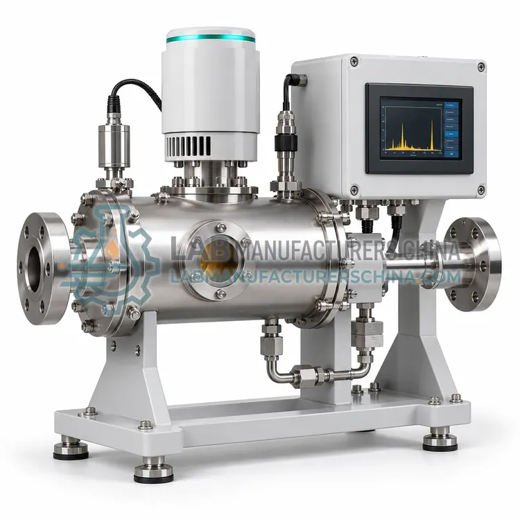
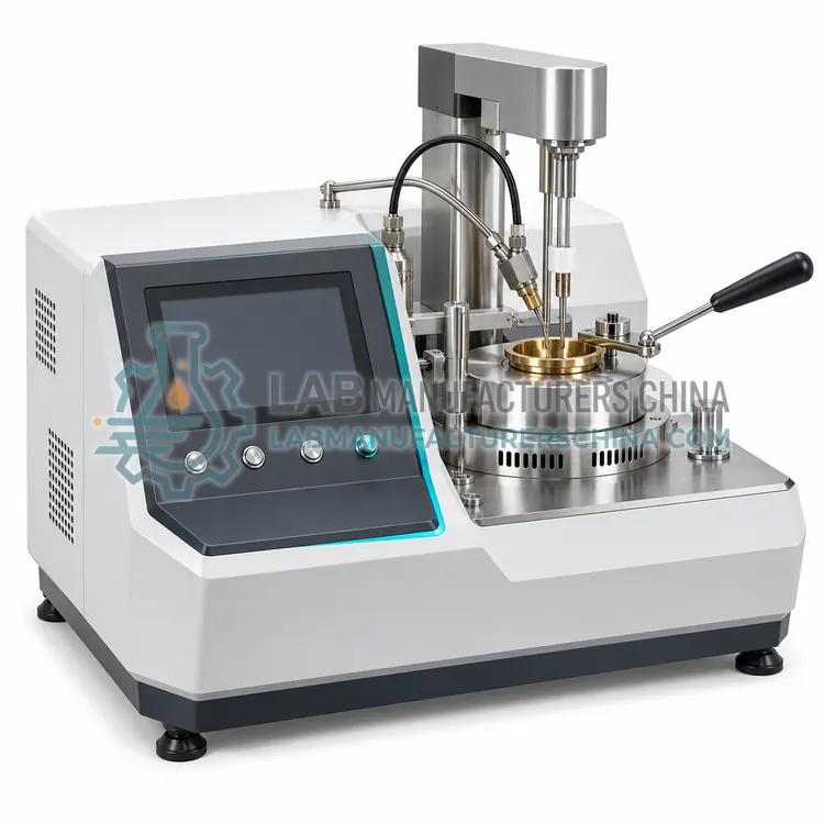
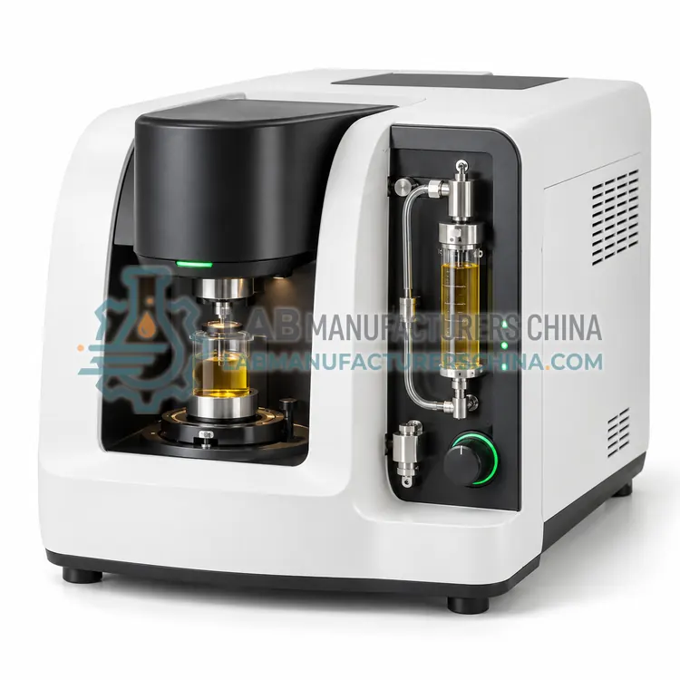
Fuel oil specifications rely on a set of physical and chemical tests. Density is obtained by oscillating U-tube: the natural frequency of a tube filled with oil depends on its mass, so period is converted to density at 15 degrees Celsius. Sulfur is measured by energy-dispersive X-ray fluorescence, where X-rays excite sulfur atoms and the intensity of the S K-alpha line, calibrated against standards, gives mass percent. Flash point is determined by heating oil in a closed Pensky-Martens cup with stirring and applying an ignition source at intervals until the vapor flashes. Micro carbon residue is obtained by thermally decomposing a weighed sample under nitrogen at 500 degrees Celsius. Water and sediment are separated by centrifuging fuel with solvent and reading the volume of the settled layer.
What are the key features?
- Four to eight 100 mL tube positions with swing-out buckets
- Relative centrifugal force over 800 at tube tip
- Heated chamber to 60 °C with temperature control
- Timer, speed control and lid interlock
- Compatible with shatter-resistant graduated tubes
What are the technical specifications?
A typical water and sediment centrifuge for fuel oil configuration offers number of tubes of 4, 6 or 8 × 100 mL, relative centrifugal force of ≥ 800 at tip (up to 1500), speed range of 500–4000 rpm, temperature control of Ambient to 65 °C, ± 3 °C, timer of 1–99 min and tube readability of 0.05 mL (0–1 mL), 0.1 mL beyond. Values are indicative of the product class; the exact figures for each configuration are confirmed on the quotation and the calibration documents supplied with the instrument.
Which applications is it used for?
The Water and Sediment Centrifuge for Fuel Oil is used in terminal and ship bunker acceptance, crude and fuel oil quantity adjustment and refinery tank quality control. Across the wider Fuel Oil Analysis class, laboratories also deploy it for bunker fuel quality verification, power plant fuel inspection and refinery blending control.
Which standards and certifications apply?
Relevant standards and methods include ISO 8217, ASTM D396, ASTM D4052, ASTM D4294, ISO 8754, ASTM D93, ISO 2719, ASTM D4530 and ASTM D4007. Certification candidates for this model are CE and ISO 9001 manufacturing; each is to be confirmed for the specific configuration before shipment, and certificates are supplied only where they have been issued.
Fuel oil samples should be representative, taken according to ISO 3170 or ASTM D4057, and heated and homogenized before analysis because heavy fuel stratifies. Instrument temperature control and cleaning between samples determine repeatability: use solvent rinses and dry thoroughly. Flash point testers require barometric pressure input and periodic verification with reference fluids. XRF analyzers need warm-up time, calibration check samples and periodic film or window replacement. Centrifuges must be balanced and located on a stable bench. Because fuel oil is flammable and samples may contain hydrogen sulfide, use good ventilation, grounding and suitable personal protective equipment.
How do I select the right Water and Sediment Centrifuge for Fuel Oil?
Select a centrifuge when free water and sediment content is a contractual or safety parameter for fuel oil. Specify tube capacity, number of positions, temperature control, compatibility with ASTM D4007 or ISO 9030 and the solvent handling requirements. For dissolved water, add a Karl Fischer titrator.
How does it compare with other Fuel Oil Analysis variants?
Select instruments according to the specification you must certify. Marine fuel compliance to ISO 8217 needs density, sulfur, flash point, carbon residue, water, sediment and viscosity, so a laboratory normally combines several instruments. For sulfur, choose an ED-XRF analyzer if your limit is 0.1 to 3.5 percent, as with marine fuels and MARPOL limits, and UV fluorescence or WD-XRF only for trace levels. For flash point, choose manual or automatic Pensky-Martens testers, and note that the automatic version improves repeatability and safety. Density meters should have temperature control and viscosity correction for heavy fuel. Also evaluate throughput, sample heating, cleaning time, calibration standards, data-management features and whether the method is accepted by your customers or port authorities.
Full specifications
| Number of tubes | 4, 6 or 8 × 100 mL |
|---|---|
| Relative centrifugal force | ≥ 800 at tip (up to 1500) |
| Speed range | 500–4000 rpm |
| Temperature control | Ambient to 65 °C, ± 3 °C |
| Timer | 1–99 min |
| Tube readability | 0.05 mL (0–1 mL), 0.1 mL beyond |
| Safety | Lid lock, imbalance detection |
| Sample volume | 50 mL fuel per tube |
| Power supply | 220 V AC, 50 Hz |
Indicative values for this product class. Final specifications are confirmed on the quotation and in the calibration documents supplied with the instrument.
Applications
- Terminal and ship bunker acceptance
- Crude and fuel oil quantity adjustment
- Refinery tank quality control
Key features
- Four to eight 100 mL tube positions with swing-out buckets
- Relative centrifugal force over 800 at tube tip
- Heated chamber to 60 °C with temperature control
- Timer, speed control and lid interlock
- Compatible with shatter-resistant graduated tubes
Frequently asked questions about Water and Sediment Centrifuge for Fuel Oil
Basic sediment and water (BS&W) is the free water and solid sediment in fuel or crude oil, reported as volume percent. It indicates contamination that can corrode equipment, foul filters and reduce calorific value.
Toluene dissolves the oil, reduces viscosity and promotes separation of water and sediment at the tube tip. It must be water-saturated to prevent it from dissolving water from the sample, and handled with proper ventilation.
Tubes must be loaded symmetrically with equal mass, using counterbalance tubes filled to the same level if an odd number is used. Imbalance causes vibration, poor separation and risk of tube breakage.
ISO 8217 lists density, kinematic viscosity, flash point, sulfur, carbon residue, water, sediment, ash, pour point and other parameters. Laboratories combine density meters, sulfur analyzers, flash point testers, viscometers and carbon residue testers to assess compliance.
Sulfur in residual fuel is usually measured by ED-XRF following ISO 8754 or ASTM D4294. The fuel is placed in a cell with a thin film, irradiated with X-rays and sulfur fluorescence intensity is compared with calibration standards.
Flash point indicates the temperature at which fuel vapors can ignite, so it defines safe storage and handling conditions. SOLAS requires marine fuels to have a minimum flash point of 60 degrees Celsius for safety.
Related models