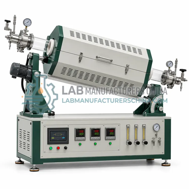
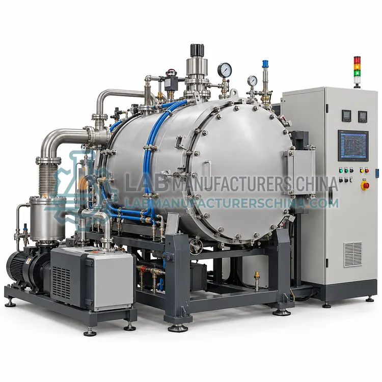
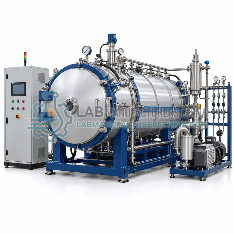
Vacuum Brazing Furnace
真空钎焊炉
- SKU VAF-0003
- Vacuum Furnaces
- CE (to be confirmed)
- ISO 9001 manufacturing (to be confirmed)
- RoHS (to be confirmed)
Price on request — FOB / CIF quoted per order
Prices depend on configuration, quantity and destination port.
Key specifications
| Hot zone size | 400×400×600 to 900×900×1200 mm |
|---|---|
| Maximum temperature | 800–1200 C |
| Working vacuum | 0.001–10 Pa |
| Hot zone material | Graphite felt or molybdenum shield |
| Temperature uniformity | ±3–5 C |
| Zone control | 2–3 zones |
Request a quote Download brochure · to be provided
By Lab Manufacturers China Technical TeamLast reviewed Standards: IEC 61010-1, IEC 60519-1, AMS 2750
What is the Vacuum Brazing Furnace?
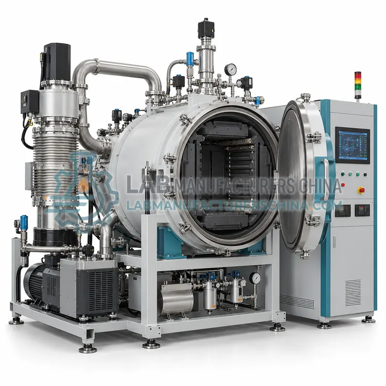
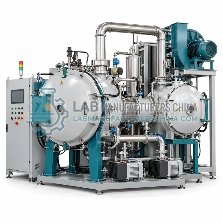
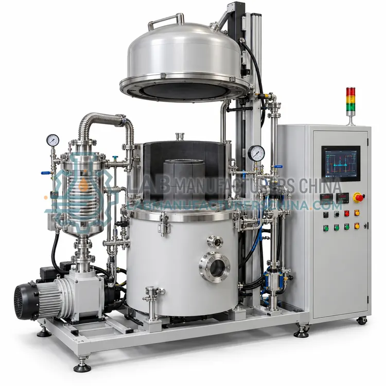
A vacuum brazing furnace joins metal assemblies with filler metal at 800 to 1200 C without flux. It is chosen for complex, multi-joint components that must be clean, leak-tight and free of flux residues.
What is the Vacuum Brazing Furnace?
A vacuum brazing furnace joins metal assemblies with filler metal at 800 to 1200 C without flux. It is chosen for complex, multi-joint components that must be clean, leak-tight and free of flux residues.
Overview
The vacuum brazing furnace heats assemblies above the filler-metal melting point in vacuum, so the filler flows by capillary action into joints without flux. Absence of oxygen prevents oxide films that block wetting, giving strong, leak-tight joints with clean surfaces. Hot zones of graphite or molybdenum reach 800 to 1200 C, and vacuum of 0.001 to 10 Pa is typical. Temperature uniformity matters greatly, since large assemblies must reach brazing temperature evenly, so multi-zone control and uniformity of plus or minus 5 C or better are used. Controlled cooling avoids thermal stress in dissimilar metals. It serves heat exchangers, aerospace assemblies, vacuum components and cutting tools, with aluminum brazing at lower temperature also common.
How does it work?
A vacuum furnace removes the chamber atmosphere with a pump system, typically a rotary-vane or dry pump backed by a roots or diffusion pump, down to rough or high vacuum. With oxygen and nitrogen largely removed, heated materials resist oxidation and outgassing, and volatile species leave the surface. Heating comes from graphite, molybdenum or tungsten elements, or from induction coils, arranged around a hot zone insulated with graphite felt or rigid insulation. Radiation is the dominant heat-transfer mode, so loads must have a clear line of sight to the elements. Type C, N or K thermocouples or optical pyrometers measure temperature, and a programmable controller follows the cycle. Gas quenching or backfill ports allow rapid, controlled cooling after the hold.
What are the key features?
- Graphite or molybdenum hot zone for 800 to 1200 C
- Working vacuum of 0.001 to 10 Pa
- Multi-zone control for uniform brazing temperature
- Controlled cooling for dissimilar metals
- No flux required, clean joints
- Uniformity of ±5 C or better
What are the technical specifications?
A typical vacuum brazing furnace configuration offers hot zone size of 400×400×600 to 900×900×1200 mm, maximum temperature of 800–1200 C, working vacuum of 0.001–10 Pa, hot zone material of Graphite felt or molybdenum shield, temperature uniformity of ±3–5 C and zone control of 2–3 zones. Values are indicative of the product class; the exact figures for each configuration are confirmed on the quotation and the calibration documents supplied with the instrument.
Which applications is it used for?
The Vacuum Brazing Furnace is used in heat exchanger brazing, aerospace assembly joining, vacuum and semiconductor component brazing, cutting tool brazing and aluminum radiator brazing. Across the wider Vacuum Furnaces class, laboratories also deploy it for vacuum heat treatment of tool steels, brazing of aerospace components and sintering of hard metals and ceramics.
Which standards and certifications apply?
Relevant standards and methods include IEC 61010-1, IEC 60519-1, AMS 2750, AMS 2769 and ISO 9001. Certification candidates for this model are CE, ISO 9001 manufacturing and RoHS; each is to be confirmed for the specific configuration before shipment, and certificates are supplied only where they have been issued.
Install on a level, rigid floor with services for power, cooling water, compressed gas and compressed air, and provide ventilation for any exhaust and gas relief. Keep cooling water clean and temperature-controlled to protect seals and pumps. Check the furnace for leaks after every opening and before critical runs, since even small leaks oxidize surfaces and spoil vacuum. Clean hot-zone insulation and elements when contamination appears, and replace graphite parts before erosion becomes severe. Maintain pump service records, verify pyrometry and uniformity surveys on schedule, and never bypass over-temperature, water-flow or door interlocks.
How do I select the right Vacuum Brazing Furnace?
Select the vacuum brazing furnace when joints must be clean, leak-tight and free of flux residues, especially for multi-joint assemblies. Atmosphere and salt-bath brazing suit simpler parts. In the RFQ, specify brazing temperature, joint materials and filler, hot zone size, uniformity, vacuum level and cooling method.
How does it compare with other Vacuum Furnaces variants?
Choose a vacuum furnace when oxidation, contamination or outgassing rules out atmosphere processing, or when surface quality and purity matter. Define the process first: heat treatment, sintering, brazing or degassing, since each sets the temperature, vacuum level and cooling method. Set the hot zone size from load dimensions and weight, and confirm the maximum temperature against the element and insulation materials. Decide on cooling, choosing between gas quenching, backfill with inert gas or slow cooling. Specify pumping stages, leak rate, partial-pressure control and safety features. For regulated heat treatment, require pyrometry compliance and uniformity surveys, and confirm three-phase power and cooling-water supply.
Full specifications
| Hot zone size | 400×400×600 to 900×900×1200 mm |
|---|---|
| Maximum temperature | 800–1200 C |
| Working vacuum | 0.001–10 Pa |
| Hot zone material | Graphite felt or molybdenum shield |
| Temperature uniformity | ±3–5 C |
| Zone control | 2–3 zones |
| Cooling | Inert-gas backfill or forced gas |
| Pumping system | Rotary-vane, roots and diffusion |
| Heating power | 40–180 kW |
| Power supply | 380 V, 3-phase, 50/60 Hz |
Indicative values for this product class. Final specifications are confirmed on the quotation and in the calibration documents supplied with the instrument.
Applications
- Heat exchanger brazing
- Aerospace assembly joining
- Vacuum and semiconductor component brazing
- Cutting tool brazing
- Aluminum radiator brazing
Key features
- Graphite or molybdenum hot zone for 800 to 1200 C
- Working vacuum of 0.001 to 10 Pa
- Multi-zone control for uniform brazing temperature
- Controlled cooling for dissimilar metals
- No flux required, clean joints
- Uniformity of ±5 C or better
Frequently asked questions about Vacuum Brazing Furnace
Vacuum removes oxygen and prevents oxide films, so filler metal wets the joint without flux. This avoids corrosive flux residues, gives clean surfaces and produces strong, leak-tight joints, which is important for heat exchangers and vacuum components.
Uniformity of about plus or minus 3 to 5 C is common, because large assemblies must reach brazing temperature evenly or some joints fill before others. Multi-zone control and a uniformity survey with the actual load help confirm performance.
Yes, if the filler metal suits both and cooling is controlled to limit thermal stress from differing expansion. Some combinations form brittle intermetallics, so the metallurgy should be checked for the joint and service conditions before processing.
It heat-treats, sinters, brazes and degasses metals and ceramics in a sealed chamber at low pressure, avoiding oxidation and contamination. It is used for tool steels, aerospace components, hard metals and reactive metals where clean surfaces and controlled atmospheres are essential.
Rough vacuum of about 1 to 100 Pa suits many heat treatments, while sintering and brazing may use 0.001 to 0.1 Pa. Partial-pressure control with inert gas is often used to limit element evaporation and alloying-element loss at high temperature.
After the hold, inert gas such as argon or nitrogen is admitted and circulated by a high-speed blower through a heat exchanger, cooling the load at a controlled rate. The available quenching pressure, often 2 to 10 bar, sets the maximum cooling rate.
Related models