Vacuum Glovebox Antechamber
手套箱过渡舱
- SKU VAC-0005
- Vacuum Chambers
- CE (to be confirmed)
- ISO 9001 manufacturing (to be confirmed)
Price on request — FOB / CIF quoted per order
Prices depend on configuration, quantity and destination port.
Key specifications
| Volume | 5–60 L |
|---|---|
| Working vacuum | About 10–1 mbar |
| Purge gas | Nitrogen or argon |
| Doors | Outer and inner, interlocked |
| Interior material | Stainless steel 304 |
| Cycle time | 5–20 min typical |
Request a quote Download brochure · to be provided
By Lab Manufacturers China Technical TeamLast reviewed Standards: IEC 61010-1, ISO 21360, ISO 27893
What is the Vacuum Glovebox Antechamber?
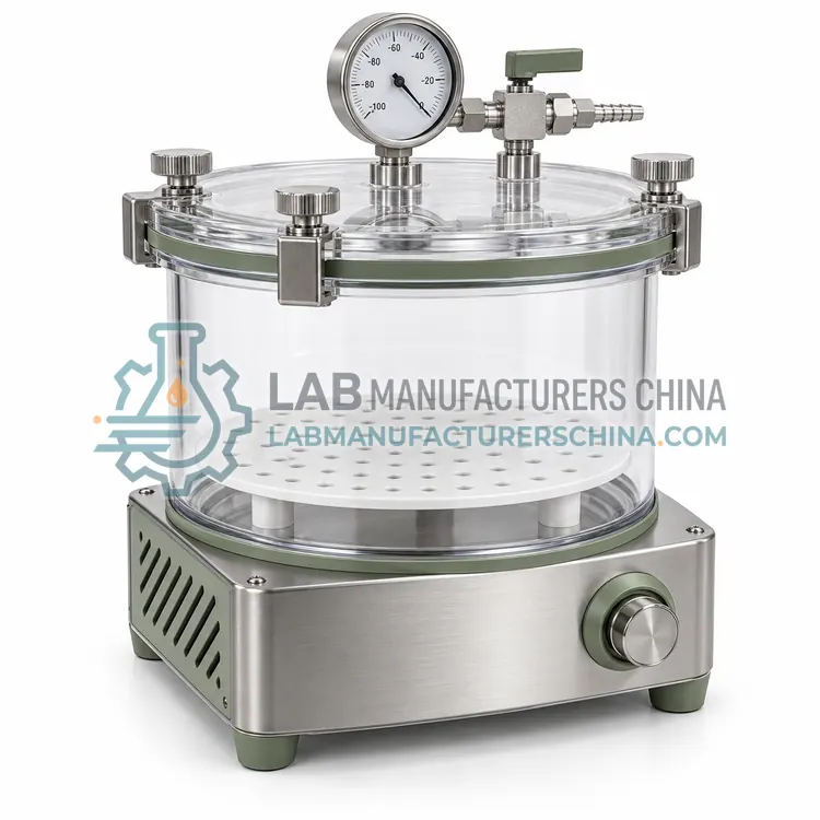
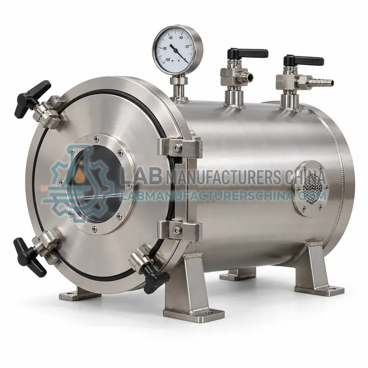
A vacuum glovebox antechamber is a small transfer chamber that lets items enter or leave a glovebox without exposing the main atmosphere. It uses vacuum and purge cycles to remove air and moisture from the transfer.
What is the Vacuum Glovebox Antechamber?
A vacuum glovebox antechamber is a small transfer chamber that lets items enter or leave a glovebox without exposing the main atmosphere. It uses vacuum and purge cycles to remove air and moisture from the transfer.
Overview
The antechamber, also called an airlock, is a compact cylindrical or rectangular chamber mounted on a glovebox. It has an outer door, an inner door and a port for vacuum and inert gas. A typical cycle draws vacuum and refills with nitrogen or argon two or three times to reduce oxygen and moisture to acceptable levels before the inner door opens. Inner doors often interlock so both cannot be open together. Volumes range from 5 to 60 liters, sized for tools, samples, small equipment and consumables. Interior surfaces are stainless steel, and a shelf or tray aids loading. Some units add heating for moisture removal. The antechamber is essential in glovebox work involving air- and moisture-sensitive chemicals, batteries, and metal or semiconductor materials.
How does it work?
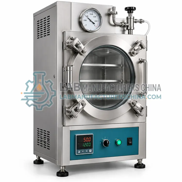
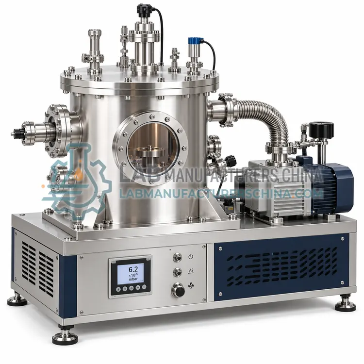
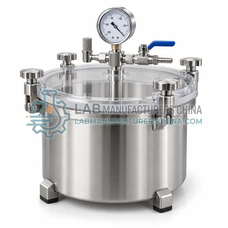
A vacuum chamber provides the sealed volume from which a pump removes gas. Its walls and seals must resist the pressure difference, which at full vacuum is about one bar acting inward on every square centimeter. Chamber materials, usually stainless steel, aluminum, acrylic or glass, determine strength, chemical resistance and outgassing behavior. Seals in O-ring grooves, gaskets or flat flanges keep air out, and the sealing method sets the achievable vacuum and the ease of opening. Ports allow connection to a pump, gauge, vent valve and feedthroughs for electrical, fluid or optical access. Internal features such as shelves, heating platens, electrodes or sample holders adapt the chamber to its task. The pump-down rate depends on chamber volume, pump speed and the conductance of the connecting line, so the chamber and pump must be matched.
What are the key features?
- Outer and inner doors with interlock
- Vacuum and inert gas purge cycles
- Volumes of 5–60 L for samples and tools
- Stainless steel interior with loading tray
- Reduces oxygen and moisture before transfer
- Optional heating for faster moisture removal
What are the technical specifications?
A typical vacuum glovebox antechamber configuration offers volume of 5–60 L, working vacuum of About 10–1 mbar, purge gas of Nitrogen or argon, doors of Outer and inner, interlocked, interior material of Stainless steel 304 and cycle time of 5–20 min typical. Values are indicative of the product class; the exact figures for each configuration are confirmed on the quotation and the calibration documents supplied with the instrument.
Which applications is it used for?
The Vacuum Glovebox Antechamber is used in air-sensitive chemical transfer, battery and cell assembly, metal and semiconductor handling, moisture-sensitive sample transfer and glovebox consumable loading. Across the wider Vacuum Chambers class, laboratories also deploy it for sample drying and desiccation, degassing of liquids and resins and vacuum coating and evaporation.
Which standards and certifications apply?
Relevant standards and methods include IEC 61010-1, ISO 21360, ISO 27893, ISO 9001 and GB 4793.1. Certification candidates for this model are CE and ISO 9001 manufacturing; each is to be confirmed for the specific configuration before shipment, and certificates are supplied only where they have been issued.
Never use a chamber above its rated pressure difference, and fit a relief valve or rupture disc where a pump could over-pressurize it or where a process generates gas. Keep sealing surfaces clean and free of scratches, and replace O-rings that are cut, swollen or hardened. Apply vacuum grease sparingly, because excess grease traps particles and can contaminate samples. Support heavy doors safely and check hinges and clamps regularly, especially on large chambers. Verify thermal uniformity if the chamber is heated, and use compatible feedthroughs for electrical or fluid lines. Follow IEC 61010-1 for associated electrical equipment and local pressure vessel rules where applicable. Record base pressure and leak-up rate during commissioning so changes can be detected later.
How do I select the right Vacuum Glovebox Antechamber?
Choose an antechamber when items must move between a glovebox and the outside without contaminating the inert atmosphere. For large equipment, a bigger or separate transfer chamber is required. In the RFQ, state glovebox model, volume, purge gas, cycle time and interlock needs.
How does it compare with other Vacuum Chambers variants?
Start with the volume needed for your samples or components, and the pressure you must reach. A desiccator-style chamber works for storage and gentle drying at rough vacuum, while ovens and coating chambers need deeper vacuum and often heating or electrode feedthroughs. Choose the material for the process: stainless steel for strength, chemical resistance and cleanability; acrylic or glass for visibility and non-magnetic work; aluminum for light weight. Confirm the pressure rating with a safety factor and check whether a relief device is needed. Select the sealing method, typically an O-ring or gasket, for the vacuum level and opening frequency, and list the ports you need for pump, gauge, vent and feedthroughs. Consider internal fixtures, door or lid access, window size and how the chamber will be cleaned and mounted.
Full specifications
| Volume | 5–60 L |
|---|---|
| Working vacuum | About 10–1 mbar |
| Purge gas | Nitrogen or argon |
| Doors | Outer and inner, interlocked |
| Interior material | Stainless steel 304 |
| Cycle time | 5–20 min typical |
| Heating option | Ambient to 120 °C |
| Pressure rating | Full vacuum to +0.5 bar |
| Mounting | Glovebox flange mount |
Indicative values for this product class. Final specifications are confirmed on the quotation and in the calibration documents supplied with the instrument.
Applications
- Air-sensitive chemical transfer
- Battery and cell assembly
- Metal and semiconductor handling
- Moisture-sensitive sample transfer
- Glovebox consumable loading
Key features
- Outer and inner doors with interlock
- Vacuum and inert gas purge cycles
- Volumes of 5–60 L for samples and tools
- Stainless steel interior with loading tray
- Reduces oxygen and moisture before transfer
- Optional heating for faster moisture removal
Frequently asked questions about Vacuum Glovebox Antechamber
Typically two or three vacuum and refill cycles to reach low oxygen and moisture levels. More cycles or a heated chamber are used when specifications are strict.
The interlock prevents both doors from opening at once, which would expose the glovebox atmosphere to air. It is a basic safety and quality feature of all antechambers.
It is designed for transfer cycles at moderate vacuum, not for prolonged vacuum processes. Use a dedicated chamber for drying, coating or degassing duties.
It depends on the material, wall thickness and design, but the limit is the pressure difference it can safely withstand, normally about one bar for a sealed vessel evacuated to rough vacuum. Follow the manufacturer rating on the label.
Stainless steel for strength, chemical resistance and cleanability; acrylic or glass for visibility and non-magnetic use; aluminum to save weight. Match the material to your samples and cleaning agents.
Common causes are a dirty or damaged O-ring, a loose flange, a poor hose connection or trapped solvent. Clean and reseal, check every joint and measure the leak-up rate with the pump isolated.
Related models