Inline Oil Particle Monitor
管路内油液颗粒监测仪
- SKU OCM-0002
- Oil Condition Monitoring
- CE (to be confirmed)
- ISO 9001 manufacturing (to be confirmed)
Price on request — FOB / CIF quoted per order
Prices depend on configuration, quantity and destination port.
Key specifications
| Particle size channels | ≥ 4, 6, 14 µm(c) |
|---|---|
| Cleanliness code range | ISO 4406 7/5/3 to 25/23/21 |
| Flow rate | 50–400 mL/min |
| Operating pressure | ≤ 350 bar |
| Oil viscosity range | ≤ 350 mm²/s |
| Oil temperature | −20 to 80 °C |
Request a quote Download brochure · to be provided
By Lab Manufacturers China Technical TeamLast reviewed Standards: ISO 4406, ISO 4407, ISO 11171
What is the Inline Oil Particle Monitor?
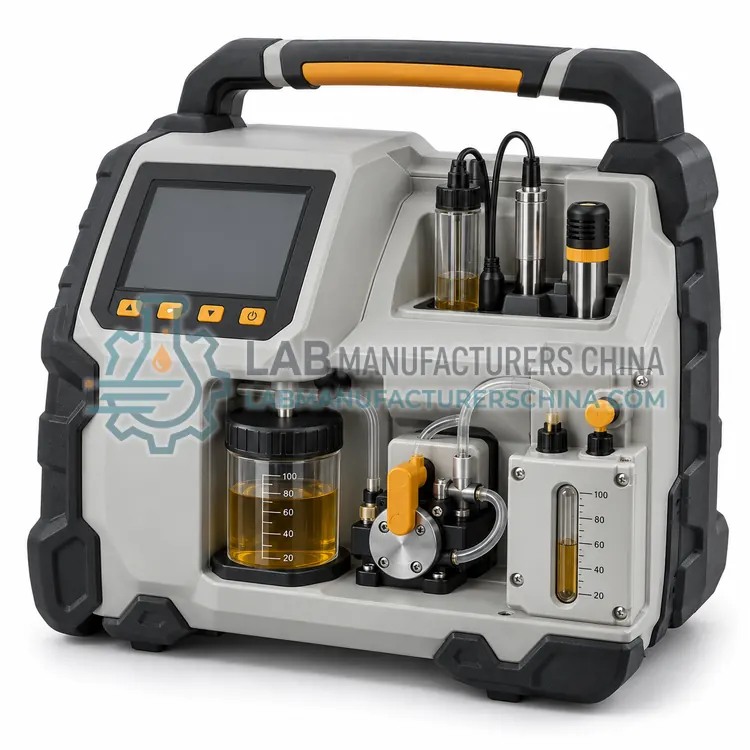
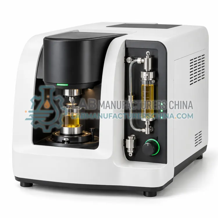
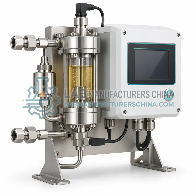
An inline oil particle monitor counts and sizes particles in a bypass flow using light extinction and reports ISO 4406 codes continuously. It supports cleanliness control of hydraulic, lubrication and transmission systems where contamination is a major cause of wear.
What is the Inline Oil Particle Monitor?
An inline oil particle monitor counts and sizes particles in a bypass flow using light extinction and reports ISO 4406 codes continuously. It supports cleanliness control of hydraulic, lubrication and transmission systems where contamination is a major cause of wear.
Overview
A small fraction of system oil passes through a precision flow cell, with flow regulated by a built-in orifice or flow controller at about 50 to 400 mL/min. A laser diode illuminates the cell and a photodetector registers the shadow cast by particles. Pulse heights are classified into size channels, typically 4, 6 and 14 micrometers(c), calibrated with ISO 11171 suspensions. The processor outputs ISO 4406 or NAS 1638 cleanliness codes at a set interval, for example every minute or every five minutes. Air bubbles and water droplets can inflate counts, so installation should be at a location with stable pressure, and some models offer bubble detection. Pressure ratings are up to 350 bar, making the unit suitable for many hydraulic systems.
How does it work?
Condition monitoring sensors convert a physical property of oil into an electrical signal. Capacitive polymer sensors measure relative humidity of oil, expressed as percent saturation, because water absorbs into a polymer film and changes its capacitance. Light-blocking or light-scattering sensors count particles in a small flow cell, from which ISO 4406 cleanliness codes are derived. Inductive coil sensors detect ferrous and non-ferrous metal particles passing through a coil by the perturbation they cause in a magnetic field. Multi-sensor probes combine dielectric constant, conductivity, temperature and viscosity, computed from resonant tuning fork or quartz crystal oscillation, to produce an oil health index. Data is logged in a controller and transmitted to a condition monitoring platform through 4-20 mA, Modbus or other protocols, where alarm thresholds and trends are evaluated.
What are the key features?
- Laser light-extinction cell calibrated to ISO 11171
- Continuous ISO 4406 and NAS 1638 output via display or fieldbus
- Pressure rating up to 350 bar for hydraulic systems
- Flow regulation built in for stable counting
- Alarm relays and data logging for trending
What are the technical specifications?
A typical inline oil particle monitor configuration offers particle size channels of ≥ 4, 6, 14 µm(c), cleanliness code range of ISO 4406 7/5/3 to 25/23/21, flow rate of 50–400 mL/min, operating pressure of ≤ 350 bar, oil viscosity range of ≤ 350 mm²/s and oil temperature of −20 to 80 °C. Values are indicative of the product class; the exact figures for each configuration are confirmed on the quotation and the calibration documents supplied with the instrument.
Which applications is it used for?
The Inline Oil Particle Monitor is used in hydraulic press and injection molding systems, steel mill and mobile equipment hydraulics and filter cart and oil-flushing verification. Across the wider Oil Condition Monitoring class, laboratories also deploy it for hydraulic system cleanliness monitoring, wind turbine gearbox oil condition monitoring and turbine lube oil water detection.
Which standards and certifications apply?
Relevant standards and methods include ISO 4406, ISO 4407, ISO 11171, ISO 17359, ISO 13374, ASTM D7647, ASTM D7917 and IEC 60079-0. Certification candidates for this model are CE and ISO 9001 manufacturing; each is to be confirmed for the specific configuration before shipment, and certificates are supplied only where they have been issued.
Install sensors at representative locations, typically in a flowing return line downstream of the component and upstream of the filter, where oil is well mixed and pressure is moderate. Avoid dead legs and ensure flow within the sensor's specified range. Configure alarms based on baseline data from new or healthy oil, not generic limits alone. Periodically verify sensor output against laboratory samples, since sensors drift or fouling can occur. Protect cables and connectors from vibration and heat, and follow hazardous-area requirements such as ATEX or IECEx where applicable. Document installation, calibration and alarm settings.
How do I select the right Inline Oil Particle Monitor?
Select an inline particle monitor when contamination control is essential to component life and immediate detection of filter failure or ingress is worthwhile. Specify pressure, viscosity, size channels, output protocol and the mounting port. It does not detect dissolved water or metal type.
How does it compare with other Oil Condition Monitoring variants?
Match the sensor to the failure modes that matter for the asset. Hydraulic and turbine systems suffer mostly from particle and water contamination, so a particle monitor and moisture sensor are the priority. Gearboxes and engines exhibit wear and oil degradation, where a wear-debris sensor and a multi-parameter probe give earlier warning. Decide between inline permanent installation and portable devices: inline gives continuous trends and alarms, while portable gives flexible coverage of many assets. Check operating pressure and temperature, installation port threads, output signals, hazardous-area approvals, calibration method and whether the sensor reports absolute values, such as ppm water, or relative trends only. Integration with existing SCADA or CMMS systems should be confirmed before purchase.
Full specifications
| Particle size channels | ≥ 4, 6, 14 µm(c) |
|---|---|
| Cleanliness code range | ISO 4406 7/5/3 to 25/23/21 |
| Flow rate | 50–400 mL/min |
| Operating pressure | ≤ 350 bar |
| Oil viscosity range | ≤ 350 mm²/s |
| Oil temperature | −20 to 80 °C |
| Output | 4–20 mA, CAN, Modbus, Ethernet |
| Ingress protection | IP67 |
| Supply voltage | 9–36 V DC |
Indicative values for this product class. Final specifications are confirmed on the quotation and in the calibration documents supplied with the instrument.
Applications
- Hydraulic press and injection molding systems
- Steel mill and mobile equipment hydraulics
- Filter cart and oil-flushing verification
Key features
- Laser light-extinction cell calibrated to ISO 11171
- Continuous ISO 4406 and NAS 1638 output via display or fieldbus
- Pressure rating up to 350 bar for hydraulic systems
- Flow regulation built in for stable counting
- Alarm relays and data logging for trending
Frequently asked questions about Inline Oil Particle Monitor
An inline monitor measures continuously on a sample stream and is calibrated for trend accuracy, while a laboratory counter measures discrete bottle samples under controlled dilution and degassing. Inline trends warn earlier; laboratory counts serve as reference.
Install on a bypass or return line after the component and before the filter, where flow is stable and pressure within range. Avoid locations with pressure spikes, air entrainment or stagnant flow.
Yes. A sudden jump in particle counts after the filter indicates bypass, damage or bad element seating. Alarm thresholds tied to ISO code targets enable maintenance before damaging particles circulate.
Oil condition monitoring tracks the health of lubricating or hydraulic oil using sensors or periodic tests, measuring water, particles, wear debris, viscosity and chemistry. Trends reveal contamination, wear or degradation early so maintenance can be planned before failure.
Online monitoring uses sensors installed on the machine to provide continuous data and alarms, while offline monitoring relies on periodic samples tested in a laboratory. Online data gives faster warning; laboratory tests give more precise and comprehensive results.
Water content, particle count and temperature are the most valuable for hydraulic and turbine systems. Wear debris, viscosity and dielectric constant add insight for gearboxes and engines. The best selection depends on the dominant failure modes of each asset.