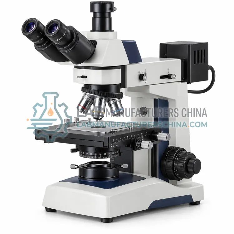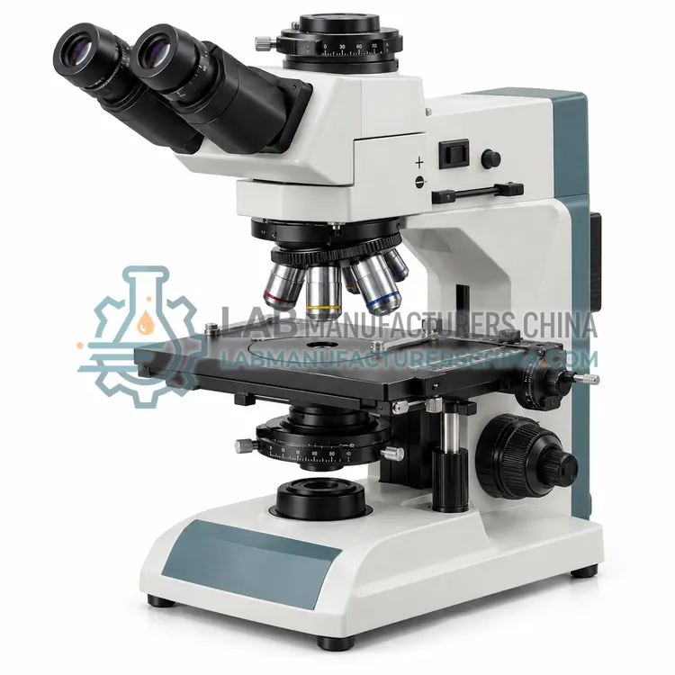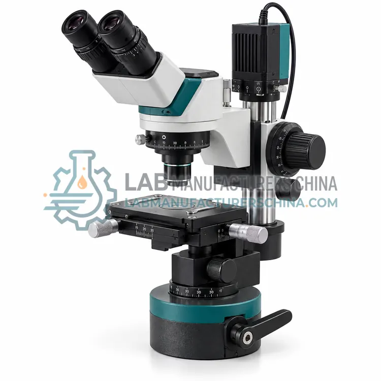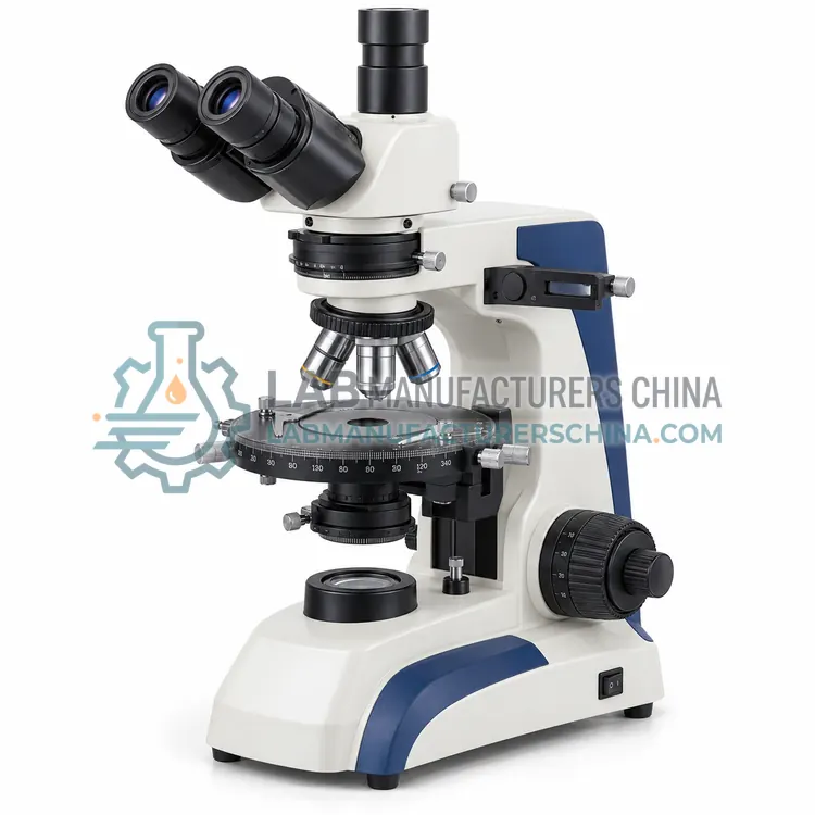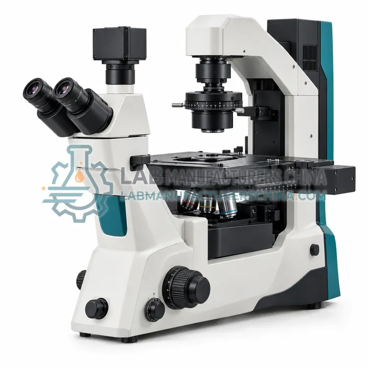
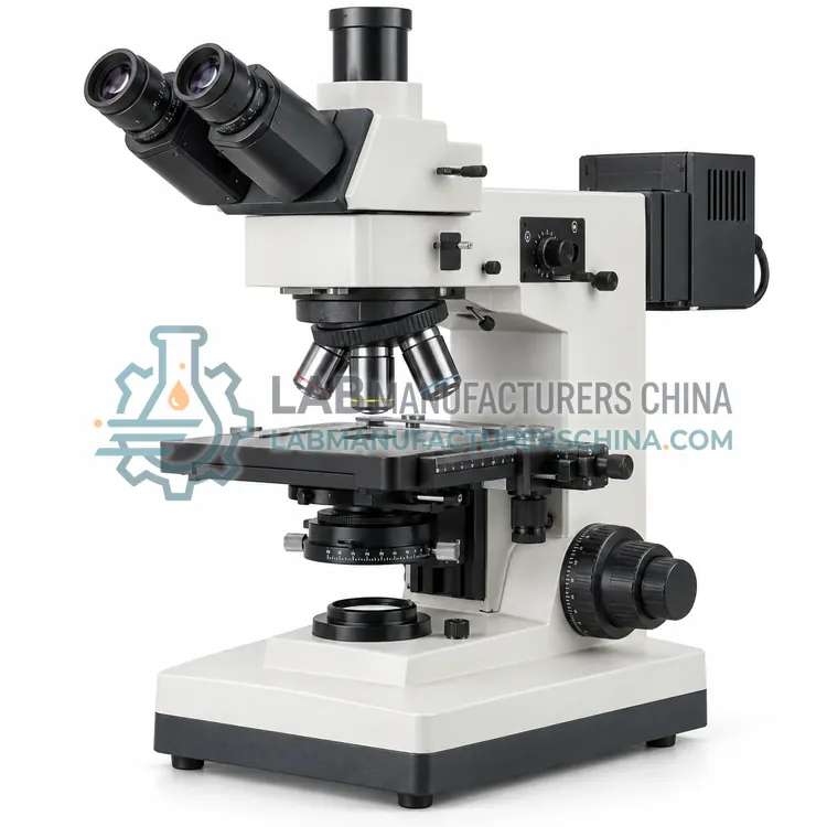
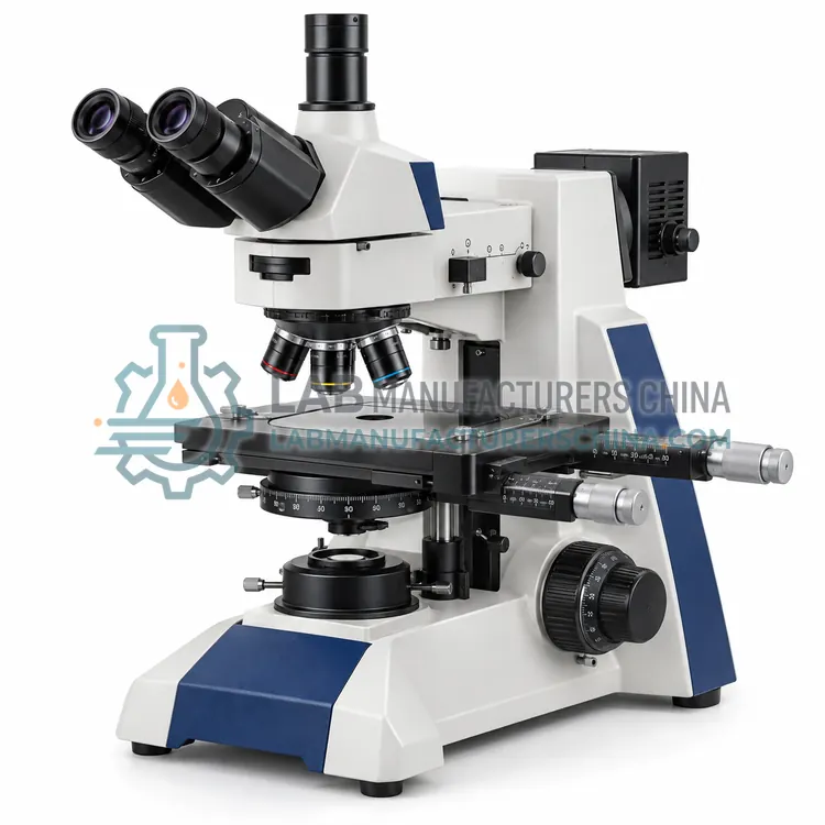
Measuring Metallurgical Microscope
测量金相显微镜
- SKU MEM-0004
- Metallurgical Microscopes
- CE (to be confirmed)
- ISO 9001 manufacturing (to be confirmed)
Price on request — FOB / CIF quoted per order
Prices depend on configuration, quantity and destination port.
Key specifications
| Optical system | Infinite corrected |
|---|---|
| Magnification range | 50×–1000× |
| Objectives | 5×, 10×, 20×, 50×, 100× plan |
| Stage measurement | X-Y micrometer or encoder |
| Stage resolution | 0.001 mm |
| Illumination | Reflected, LED or halogen |
Request a quote Download brochure · to be provided
By Lab Manufacturers China Technical TeamLast reviewed Standards: ASTM E3, ASTM E407, ASTM E112
What is the Measuring Metallurgical Microscope?
A measuring metallurgical microscope combines reflected-light observation with precise stage coordinates and measuring reticles. It is used to accurately measure dimensions, features and layer thicknesses on prepared specimens and routine industrial parts in quality control.
What is the Measuring Metallurgical Microscope?
A measuring metallurgical microscope combines reflected-light observation with precise stage coordinates and measuring reticles. It is used to accurately measure dimensions, features and layer thicknesses on prepared specimens and routine industrial parts in quality control.
Overview
A measuring metallurgical microscope adds precise, often digital, stage coordinates and measuring reticles or software to a reflected-light optical system. The stage is fitted with micrometers or linear encoders so features can be located and their distances measured in two axes, while reticles or calibrated software measure distances within the field of view. Digital readouts display coordinates, and software can overlay scales and record measurements against the image. The configuration suits measurement of coating thickness, layer structures, machined features and defect sizes, and supports documentation for quality records. Calibration against a stage micrometer is essential for traceable results.
How does it work?
A metallurgical microscope illuminates the specimen from the same side as the objective, so light reflects off the surface and returns through the objective to the eyepiece or camera. Because the sample is opaque, transmitted illumination is not used. Brightfield reflection shows phases and structures by differences in reflectivity. Darkfield uses oblique illumination to reveal scratches, edges and fine particles. Polarized light and differential interference contrast add information about anisotropy and surface relief. Specimens are usually mounted in resin, ground and polished, and often etched to reveal grain boundaries. Objective numerical aperture, illumination type and surface preparation determine what can be resolved.
What are the key features?
- Reflected-light optics for opaque specimens
- Micrometer or encoder stage for coordinate measurement
- Measuring reticles or calibrated software scales
- Digital readout of position and distance
- Calibration against traceable stage micrometers
What are the technical specifications?
A typical measuring metallurgical microscope configuration offers optical system of Infinite corrected, magnification range of 50×–1000×, objectives of 5×, 10×, 20×, 50×, 100× plan, stage measurement of X-Y micrometer or encoder, stage resolution of 0.001 mm and illumination of Reflected, LED or halogen. Values are indicative of the product class; the exact figures for each configuration are confirmed on the quotation and the calibration documents supplied with the instrument.
Which applications is it used for?
The Measuring Metallurgical Microscope is used in coating and layer thickness measurement, feature and defect size measurement, machined part dimensional checks and weld and joint geometry measurement. Across the wider Metallurgical Microscopes class, laboratories also deploy it for metals and alloys grain structure analysis, welding and heat-treatment evaluation and failure analysis and defect investigation.
Which standards and certifications apply?
Relevant standards and methods include ASTM E3, ASTM E407, ASTM E112, ISO 643 and IEC 61010-1. Certification candidates for this model are CE and ISO 9001 manufacturing; each is to be confirmed for the specific configuration before shipment, and certificates are supplied only where they have been issued.
Specimen preparation dominates image quality, so follow a consistent grinding and polishing procedure, and etch according to the relevant standard. Keep the objective and the specimen surface free of dust, oil and residue, and avoid scratching coatings. Cover the specimen when not in use to prevent oxidation and contamination. Verify the illumination alignment and, for polarized work, use strain-free objectives and a centred polarizer. Calibrate measurements with a stage micrometer for each objective and record the scale. Service the stage and focus mechanisms, and check the lamp or diode output on a schedule.
How do I select the right Measuring Metallurgical Microscope?
Choose a measuring metallurgical microscope when dimensions must be quantified, such as layer thickness or feature size. Confirm the stage measuring range and resolution suit the parts, and that reticles or software provide the required measurement functions. Ensure a traceable stage micrometer is available for calibration, and check that measurement records can be exported for quality documentation.
How does it compare with other Metallurgical Microscopes variants?
Choose a metallurgical microscope for opaque, reflective specimens examined in reflected light. Decide the contrast methods required: brightfield for general structure, darkfield for defects and fine features, and polarized light or differential interference contrast for anisotropy and relief. Confirm the stage can hold the sample format, including mounted specimens, large parts or wafers. Consider upright models for small mounted samples and inverted models for larger ones. Select plan objectives for flat fields of view and a camera suited to measurement and documentation. For grain-size or phase measurement, check that measurement software and calibration are available.
Full specifications
| Optical system | Infinite corrected |
|---|---|
| Magnification range | 50×–1000× |
| Objectives | 5×, 10×, 20×, 50×, 100× plan |
| Stage measurement | X-Y micrometer or encoder |
| Stage resolution | 0.001 mm |
| Illumination | Reflected, LED or halogen |
| Measuring reticle | Crosshair with scale, 10 mm/100 divisions |
| Digital readout | X-Y coordinate display |
| Camera port | C-mount trinocular |
| Power supply | 100–240 V AC |
Indicative values for this product class. Final specifications are confirmed on the quotation and in the calibration documents supplied with the instrument.
Applications
- Coating and layer thickness measurement
- Feature and defect size measurement
- Machined part dimensional checks
- Weld and joint geometry measurement
Key features
- Reflected-light optics for opaque specimens
- Micrometer or encoder stage for coordinate measurement
- Measuring reticles or calibrated software scales
- Digital readout of position and distance
- Calibration against traceable stage micrometers
Frequently asked questions about Measuring Metallurgical Microscope
Stage micrometers and encoder stages typically resolve to about 0.001 mm, and measurement uncertainty also depends on objective calibration, edge definition and operator judgment. Under good conditions, measurements within a few micrometres are achievable, but the uncertainty should be stated in the record.
Yes. After calibration with a stage micrometer, image-analysis software can draw lines and regions on the image and report distances and areas directly. Software measurement is convenient for documentation but still depends on correct calibration and consistent edge detection.
Stage measurement uses the physical movement of a calibrated stage, so it is limited by stage accuracy and travel and is well suited to larger distances. Image measurement uses calibrated pixels within a single field and suits small features, but must be recalibrated whenever magnification or camera changes.
Metals, alloys and many ceramics are opaque, so light cannot pass through them. A metallurgical microscope therefore illuminates the polished surface through the objective and collects the reflected light. Transparent petrographic specimens are examined differently, with transmitted polarized light.
Specimens are usually cut, mounted in resin, ground and polished to a mirror finish, then etched to reveal grain boundaries and phases. Preparation steps follow standards such as ASTM E3 and ASTM E407. Poor preparation introduces scratches and artefacts that can be mistaken for real features.
Darkfield highlights edges, scratches, inclusions and fine particles that reflect or scatter light obliquely. It increases defect visibility in polished surfaces and is useful for detecting small features that brightfield may miss, though it is not used for general structure assessment.
Related models