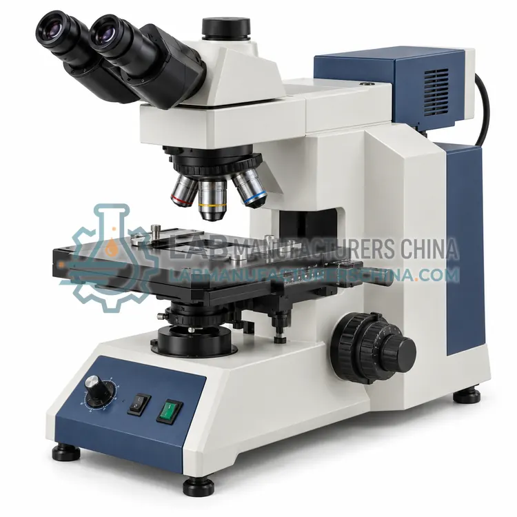
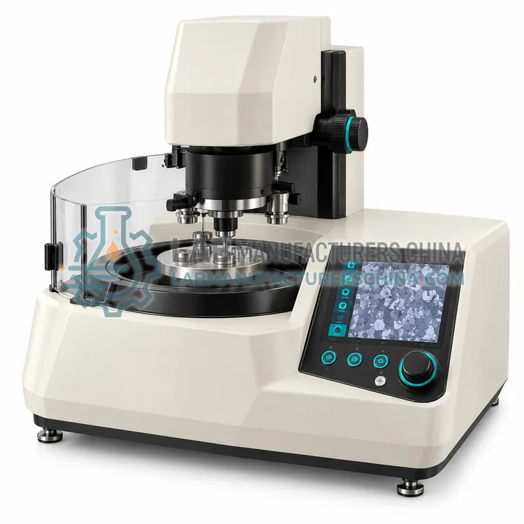
Metallographic Image Analysis System
金相图像分析系统
- SKU MEE-0002
- Metallographic Equipment
- CE (to be confirmed)
- ISO 9001 manufacturing (to be confirmed)
Price on request — FOB / CIF quoted per order
Prices depend on configuration, quantity and destination port.
Key specifications
| Camera resolution | 5–20 megapixels |
|---|---|
| Calibration | Stage micrometer per objective |
| Grain size methods | Intercept and planimetric |
| Phase fraction output | Area percent with confidence limits |
| Coating thickness | Multiple measurements per section |
| Stage automation | Optional motorized scanning stage |
Request a quote Download brochure · to be provided
By Lab Manufacturers China Technical TeamLast reviewed Standards: ASTM E3, ASTM E407, ASTM E112
What is the Metallographic Image Analysis System?
A metallographic image analysis system captures microscope images and applies calibrated measurement routines to quantify grain size, phase fractions, nodularity, inclusion ratings and coating thickness. It converts visual assessment into repeatable numbers for acceptance testing.
What is the Metallographic Image Analysis System?
A metallographic image analysis system captures microscope images and applies calibrated measurement routines to quantify grain size, phase fractions, nodularity, inclusion ratings and coating thickness. It converts visual assessment into repeatable numbers for acceptance testing.
Overview
A digital camera captures the field of view and software segments the image into features of interest using grey-level thresholds, colour or edge detection. Measurements follow standard definitions: grain size by the intercept or planimetric method of ASTM E112 and ISO 643, phase and nodularity fractions by area, inclusion content by comparison or counting procedures such as ASTM E45 and ISO 4967, and coating thickness along lines normal to the surface. Automatic scanning stages build mosaics of large areas so that measurements are statistically meaningful rather than based on one field, and routines can be saved as methods with fixed thresholds, magnification and acceptance limits so that different operators obtain the same result. The system also stores images with the specimen identity, making reports traceable and allowing later re-measurement if a question arises.
How does it work?
Metallography reveals the internal structure of a metal by preparing a flat, scratch-free surface and then accentuating features chemically or optically. A cut-off wheel sections the specimen under coolant so heat does not alter the structure, and hot or cold mounting encapsulates it in resin for handling. Grinding with silicon carbide papers removes the cut damage, and polishing with diamond or alumina suspensions produces a mirror-like surface. Etching with a reagent such as nital attacks grain boundaries and specific phases preferentially, so reflected light shows grain structure, phase contrast and defects. Examination uses inverted or upright reflected-light microscopes with brightfield, darkfield, polarized and differential interference contrast modes, and images are captured digitally. Image analysis then measures grain size by intercept or planimetric methods, phase fractions, nodularity, inclusion ratings and coating thickness, producing numbers that can be compared against acceptance limits.
What are the key features?
- Calibrated digital camera on the microscope port
- Threshold and edge based feature segmentation
- Grain size routines to ASTM E112 and ISO 643
- Inclusion rating to ASTM E45 and ISO 4967
- Coating thickness measurement along normal lines
- Saved methods with fixed thresholds and limits
What are the technical specifications?
A typical metallographic image analysis system configuration offers camera resolution of 5–20 megapixels, calibration of Stage micrometer per objective, grain size methods of Intercept and planimetric, phase fraction output of Area percent with confidence limits, coating thickness of Multiple measurements per section and stage automation of Optional motorized scanning stage. Values are indicative of the product class; the exact figures for each configuration are confirmed on the quotation and the calibration documents supplied with the instrument.
Which applications is it used for?
The Metallographic Image Analysis System is used in grain size and phase fraction reporting, inclusion and cleanliness rating of steels, coating and case depth measurement, nodularity assessment in cast iron and batch reporting for production control. Across the wider Metallographic Equipment class, laboratories also deploy it for microstructure examination in steel and cast iron, grain size and phase fraction measurement and inclusion and cleanliness rating.
Which standards and certifications apply?
Relevant standards and methods include ASTM E3, ASTM E407, ASTM E112, ASTM E45, ASTM E562, ISO 643 and IEC 61010-1. Certification candidates for this model are CE and ISO 9001 manufacturing; each is to be confirmed for the specific configuration before shipment, and certificates are supplied only where they have been issued.
Consumables dominate metallographic quality, so keep an adequate stock of cut-off wheels, resin, papers, cloths and diamond suspensions, and follow the supplier's recommended sequence. Clean specimens thoroughly between steps with water and alcohol and dry them before etching, since contamination produces artefacts. Prepare a batch of control specimens of known structure to check that the procedure still reveals the true structure, and date all etchants, replacing them when they weaken. Verify microscope calibration with a stage micrometer each time magnification is changed, and confirm that the software's length scale matches the objective actually used. Handle etchants and solvents with gloves, eye protection and fume extraction, and dispose of spent solutions through an authorised route, since many contain strong acids or organic solvents.
How do I select the right Metallographic Image Analysis System?
Select the image analysis system when results must be numeric, repeatable and traceable, and check that the software implements the methods you report. Specify camera resolution, calibration accessories, automation options and the report formats required by your quality system.
How does it compare with other Metallographic Equipment variants?
Choose preparation equipment by specimen type and daily volume. Hardened steel and large sections need a sturdy cut-off saw with adequate cooling, while small or porous parts need vacuum impregnation or cold mounting. A semi-automatic grinding and polishing head with individual force control gives reproducible results for several specimens at once and is worth the cost when many samples are prepared daily. For examination, decide whether an upright microscope is enough or whether an inverted stage is needed for large, unmounted samples, and check the magnification range, illumination modes and camera resolution against the features you measure. Image analysis software should support the specific measurements you report, such as ASTM E112 grain size, ASTM E45 inclusion ratings or coating thickness, and it should allow the measurement rules and thresholds to be recorded so results can be audited and reproduced by another operator.
Full specifications
| Camera resolution | 5–20 megapixels |
|---|---|
| Calibration | Stage micrometer per objective |
| Grain size methods | Intercept and planimetric |
| Phase fraction output | Area percent with confidence limits |
| Coating thickness | Multiple measurements per section |
| Stage automation | Optional motorized scanning stage |
| Report output | Images, tables, CSV and PDF |
| Licence | Single or network workstation |
Indicative values for this product class. Final specifications are confirmed on the quotation and in the calibration documents supplied with the instrument.
Applications
- Grain size and phase fraction reporting
- Inclusion and cleanliness rating of steels
- Coating and case depth measurement
- Nodularity assessment in cast iron
- Batch reporting for production control
Key features
- Calibrated digital camera on the microscope port
- Threshold and edge based feature segmentation
- Grain size routines to ASTM E112 and ISO 643
- Inclusion rating to ASTM E45 and ISO 4967
- Coating thickness measurement along normal lines
- Saved methods with fixed thresholds and limits
Frequently asked questions about Metallographic Image Analysis System
Calibration of the magnification scale, image quality, threshold settings, the number of fields measured and the preparation quality of the specimen. Documented methods with fixed parameters are essential for comparability.
Enough to make the result statistically representative, which depends on structure uniformity and is stated in the relevant standard. Automated scanning of a large area is preferred where the structure varies across the section.
Not entirely. Preparation quality, etching, feature definition and threshold selection all require technical judgement, and results must be verified visually. Software improves repeatability once the method is fixed and validated.
Sectioning with a cooled abrasive wheel, mounting in resin, coarse grinding, fine grinding on successively finer papers, polishing with diamond or alumina suspension, and etching if structure is to be revealed. Cleaning and drying follow each stage.
By comparing the etched structure with standard charts, or by counting grain boundary intersections along test lines and converting the count to a grain size number, as described in ASTM E112 and ISO 643.
For soft, ductile or difficult metals that smear or deform during mechanical polishing, and for preparing surfaces for electron microscopy. It removes material uniformly, but the electrolyte must be matched to the alloy and temperature controlled.
Related models