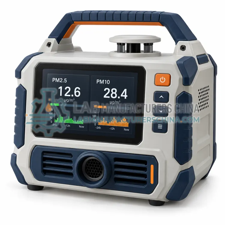
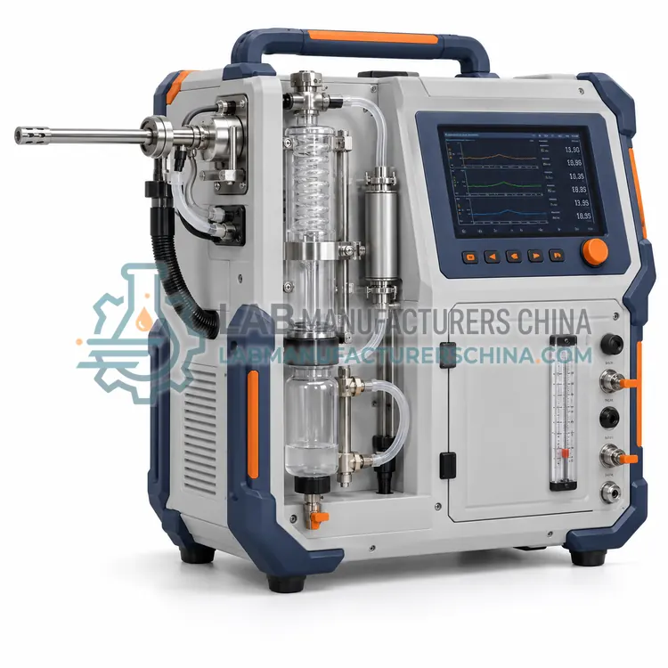
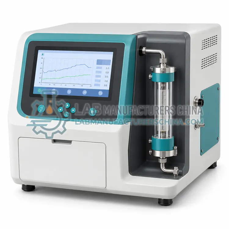
Stack Gas Flow and Velocity Monitor
烟气流量和流速监测仪
- SKU EMM-0005
- Emission Monitoring
- CE (to be confirmed)
- EN 15267-3 QAL1 (to be confirmed)
- China CEMS certification (to be confirmed)
Price on request — FOB / CIF quoted per order
Prices depend on configuration, quantity and destination port.
Key specifications
| Velocity range | 0.5–40 m/s |
|---|---|
| Accuracy | ±2% of reading (after calibration) |
| Duct diameter | 0.3–15 m |
| Process temperature | −20 to 400 °C |
| Pressure range | ±5 kPa |
| Response time | ≤ 5 s |
Request a quote Download brochure · to be provided
By Lab Manufacturers China Technical TeamLast reviewed Standards: EN 14181, EN 15267-3, EN 15259
What is the Stack Gas Flow and Velocity Monitor?
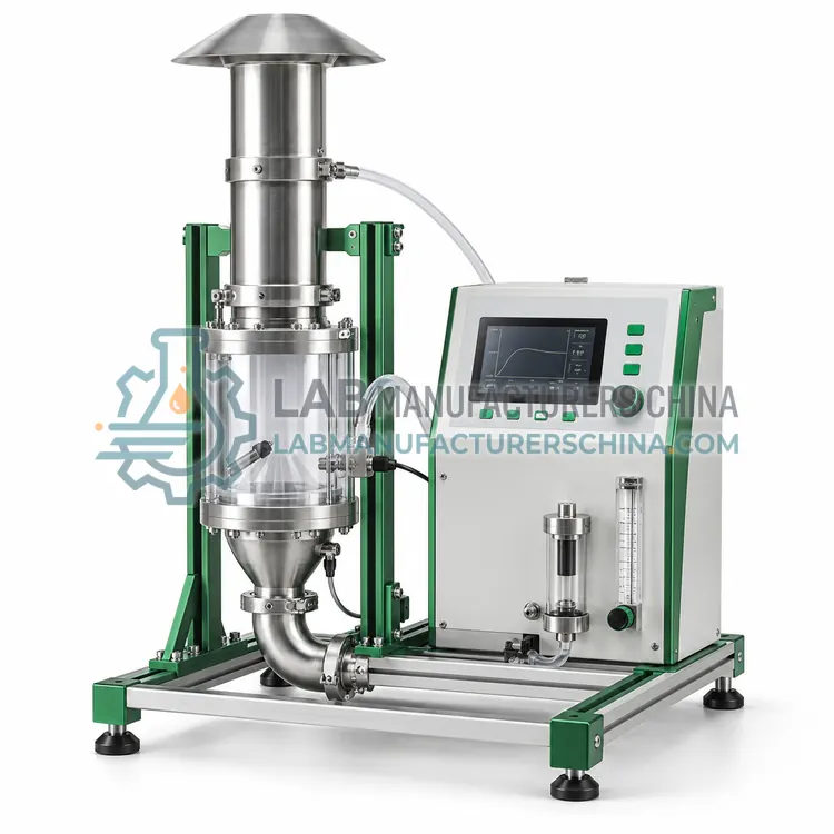
A monitor that measures gas velocity, temperature and volumetric flow in a stack using ultrasonic transit time, differential pressure pitot tubes or thermal mass sensing. It is the right choice for converting concentrations into mass emission rates for regulatory reporting and emission trading.
What is the Stack Gas Flow and Velocity Monitor?
A monitor that measures gas velocity, temperature and volumetric flow in a stack using ultrasonic transit time, differential pressure pitot tubes or thermal mass sensing. It is the right choice for converting concentrations into mass emission rates for regulatory reporting and emission trading.
Overview
Emission limits are often expressed in kg per hour or tonnes per year, which requires stack flow. Ultrasonic transit-time flow meters send pulses between two transducers mounted diagonally across the duct, and the difference in upstream and downstream travel time gives velocity, with no obstruction and low maintenance. Pitot-tube systems measure differential pressure, need a backflush system to prevent clogging and suit clean, low-velocity stacks. Thermal mass probes suit low-velocity flows in ducts. The flow monitor is calibrated by a velocity traverse using a reference S-type pitot probe under ISO 10780 or EN ISO 16911-1, and the profile factor is entered. Temperature, pressure and moisture inputs convert actual flow to normal dry flow for emission calculations.
How does it work?
Emission monitors determine pollutants in hot, wet and dusty flue gas. Extractive systems withdraw a sample through a heated probe and line at 180 °C, remove particles with a filter, and either keep the gas hot for analysis or dry it in a chiller before measurement. Analyzers use non-dispersive infrared for CO, CO2 and SO2, chemiluminescence or UV for NOx, paramagnetic or zirconia cells for O2, and FTIR for multi-component measurement. In-situ systems measure across the stack using tunable diode laser absorption or UV. Particulate monitors use light scattering, transmissometry for opacity, or triboelectric signals, and flow is measured by differential pressure pitot tubes or ultrasonic transit time. A data acquisition system normalizes values to reference oxygen, dry basis and standard conditions, applies calibration and reports averages.
What are the key features?
- Ultrasonic transit-time design has no obstruction and negligible pressure drop.
- Automatic backflush keeps pitot ports clear in dusty stack conditions.
- Temperature and pressure compensation converts actual flow to normal dry flow.
- Velocity profile factor entry corrects for non-uniform stack flow distribution.
- Digital and analog outputs feed CEMS data loggers for mass emission rate calculation.
- Sensors withstand flue gas temperature up to 400 °C with optional cooling.
What are the technical specifications?
A typical stack gas flow and velocity monitor configuration offers velocity range of 0.5–40 m/s, accuracy of ±2% of reading (after calibration), duct diameter of 0.3–15 m, process temperature of −20 to 400 °C, pressure range of ±5 kPa and response time of ≤ 5 s. Values are indicative of the product class; the exact figures for each configuration are confirmed on the quotation and the calibration documents supplied with the instrument.
Which applications is it used for?
The Stack Gas Flow and Velocity Monitor is used in mass emission rate reporting, emission trading and tax calculation, combustion air balance monitoring and ventilation duct flow control. Across the wider Emission Monitoring class, laboratories also deploy it for coal and gas power plant stacks, cement and lime kiln emissions and waste incineration monitoring.
Which standards and certifications apply?
Relevant standards and methods include EN 14181, EN 15267-3, EN 15259, ISO 12039, US EPA 40 CFR Part 60, US EPA 40 CFR Part 75, HJ 75 and HJ 76. Certification candidates for this model are CE, EN 15267-3 QAL1 and China CEMS certification; each is to be confirmed for the specific configuration before shipment, and certificates are supplied only where they have been issued.
Choose sampling locations that meet EN 15259 or HJ/T 397 requirements for straight duct length and port access, because flow profile affects representativeness. Keep heated lines above the acid dew point to prevent condensation and corrosion, and replace probe filters and pump heads regularly. Perform daily automatic zero and span checks, quarterly or annual linearity checks, and an annual surveillance test against a standard reference method under EN 14181 QAL3 and AST. Protect cabinets from dust and temperature extremes, and provide calibration gas cylinders with certified uncertainties. Keep records of maintenance, calibration and data substitution, since regulators audit these, and train operators in safe work on platforms.
How do I select the right Stack Gas Flow and Velocity Monitor?
Select a flow monitor whenever limits are in mass units or flow must be reported with concentrations. Ultrasonic suits large, dusty ducts, pitot suits small clean ones. In an RFQ, specify duct diameter, temperature, velocity range, dust level, available compressed air and calibration support.
How does it compare with other Emission Monitoring variants?
Start with the regulated pollutants, emission limits and the standard your permit cites, such as EN 14181 or HJ 75. Decide between extractive and in-situ systems according to stack temperature, moisture, acid gas content and the number of species: extractive suits multi-component and low-level measurements, while in-situ suits single gases and fast response. Check that measurement ranges are suitable for the limits, with limits in the lower third of the range where possible. Consider reporting requirements for averaging, data validation and certified instrument status under schemes such as EN 15267 or China CEMS certification. Include sample conditioning maintenance, calibration gas logistics, shelter size and the ability to cope with wet scrubber stacks.
Full specifications
| Velocity range | 0.5–40 m/s |
|---|---|
| Accuracy | ±2% of reading (after calibration) |
| Duct diameter | 0.3–15 m |
| Process temperature | −20 to 400 °C |
| Pressure range | ±5 kPa |
| Response time | ≤ 5 s |
| Measurement principle | Ultrasonic transit time or pitot differential pressure |
| Outputs | 4–20 mA, RS-485 Modbus |
| Purge or backflush | Compressed air, 4–6 bar |
| Ingress protection | IP65 |
Indicative values for this product class. Final specifications are confirmed on the quotation and in the calibration documents supplied with the instrument.
Applications
- Mass emission rate reporting
- Emission trading and tax calculation
- Combustion air balance monitoring
- Ventilation duct flow control
Key features
- Ultrasonic transit-time design has no obstruction and negligible pressure drop.
- Automatic backflush keeps pitot ports clear in dusty stack conditions.
- Temperature and pressure compensation converts actual flow to normal dry flow.
- Velocity profile factor entry corrects for non-uniform stack flow distribution.
- Digital and analog outputs feed CEMS data loggers for mass emission rate calculation.
- Sensors withstand flue gas temperature up to 400 °C with optional cooling.
Frequently asked questions about Stack Gas Flow and Velocity Monitor
Concentration alone cannot give total emissions. Multiplying concentration by normalized volumetric flow yields mass per hour or year, which is the basis for permit limits, emission trading and environmental taxes.
Verification compares its velocity with a multi-point traverse using a reference S-type pitot tube under ISO 10780 or EN ISO 16911-1. The ratio is stored as a calibration factor and is checked annually during surveillance tests.
Normal cubic meters (Nm³) express gas volume at standard conditions, usually 273.15 K and 101.325 kPa, dry basis, and often at reference oxygen content. This enables comparison across different temperatures, pressures and moisture levels.
A CEMS is an installed system that continuously measures pollutant concentrations and flow in stack gas, normalizes the results to reference conditions and records them for regulatory reporting. It typically includes a sampling system, gas analyzers, dust monitor, flow meter and data acquisition software.
Flue gas contains water vapor and acid gases such as SO2 and HCl that dissolve in condensate. Heating the probe and line to about 180 °C keeps the gas above the dew point, preventing loss of soluble species and corrosion before the sample reaches the analyzer.
Under EN 14181, QAL3 is ongoing quality assurance by the plant operator, using control charts of zero and span drift to show the measuring system remains within its uncertainty. It is complemented by QAL1 suitability testing, QAL2 calibration and annual surveillance tests.